
|
|
SUBSIM: The Web's #1 resource for all submarine & naval simulations since 1997
|
SUBSIM: The Web's #1 resource for all submarine & naval simulations since 1997 |
 12-30-08, 01:45 AM
|
#406 | |
|
Admiral
 Join Date: Mar 2007
Posts: 2,200
Downloads: 172
Uploads: 0
|
Quote:
__________________
What we do in life echoes in Eternity |
|

|

|
|
12-30-08, 11:35 AM
|
#407 |
|
Ocean Warrior
 Join Date: Jul 2007
Location: Kalamazoo, MI
Posts: 3,243
Downloads: 108
Uploads: 0
|
so you planing any other boats for this treatment?
__________________
Member of the Subsim Zombie Army |
|
|
|
|
12-30-08, 05:16 PM
|
#408 |
|
Watch
 Join Date: Dec 2006
Location: Bedford, UK.
Posts: 25
Downloads: 9
Uploads: 0
|
I've just stumbled across this video on YouTube, at 0:48, there's a short few seconds of black and white footage shot in 1941 of the engine's pushrods and rocker arms in motion - might perhaps be of use in making the animation more realistic. |
|
|
|
|
12-31-08, 10:48 PM
|
#409 |
|
Watch
Join Date: May 2005
Posts: 21
Downloads: 41
Uploads: 0
|
"The question now remains though, which 2 are used for inlet, the outer 2 :?
[edit] Ok, by looking at the screenshots in this thread again, I think we can say the outer two run in sync." The link below seems to be a 2-cylinder MWM version of the 6-cylinder MWM used in Type IIs. Notice that the center rocker is not moving. It's not even really a rocker arm--more of a half rocker. There's also something odd about its spring arrangment: it doesn't actually align with the other springs, but more under the "cup" between the other two rockers. Look carefully at the other photos in this thread, and you'll notice they actually agree with the clip (Half a rocker. Springs are not like the others). After some more research, I think it is part of a cam-operated pneumatic starter. The push rods open an air valve to push each piston down in the correct order for starting. The push rods are probably driven by the same cam that drives the valves (maybe even by the same intake lobes), but the "air" push rods are held off the lobes during running. I think you could save some polys, and certainly save some animation work (at least during normal running). I would still go with your current solution until it is definitively disproven. Thanks for this by the way. Last edited by Buster_Dee; 12-31-08 at 11:54 PM. |
|
|
|
|
01-01-09, 06:24 AM
|
#410 |
|
The Old Man
 Join Date: Apr 2007
Location: Netherlands
Posts: 1,549
Downloads: 26
Uploads: 3
|
Good find. You may be right, by looking at the screenshots it indeed looks the same as to what you describe. Too bad the video is so short...
In this case, Tomi should redesign the center arm.
__________________
 SH5 mods: Speech Recognition for SH5 | Digital UI Clock Tutorials: [TEC] Import/export 3D models to/from game using S3D [TEC] How to work with the model viewer in S3D - VIDEO |
|
|
|
|
01-01-09, 08:35 AM
|
#411 |
|
Lucky Jack
 
Join Date: Jun 2005
Location: In a 1954 Buick.
Posts: 28,267
Downloads: 90
Uploads: 0

|
First of all, let just say WOW, just WOW. Amongst all the awesome mods created this one is simply ground breaking. I can not say enough to the work put into this engine and engine animation.
I read through everyone's take on the valve trains, intake valve and exhaust valve configuration. All are very valid set up for valve train operation. The three valve intake IMO would have to be two intake valves that should open at the same time and the third valve would be the exhaust valve just in a larger diameter to acommodate the volumn of burnt gases the intake valves allow to enter the combustion chamber. However, the third rocker/valve assembly could just be the injector port for the fuel. I would not suspect the third valve to be an injection valve for compressed air to start the motor because mechanical knowledge of shutting down valves off camshafts and collapsable lifters were not yet designed. I could be wrong but believe I'm correct. Solid lifters were used well into the 80's and shutting down valves while in operation I believe was not designed until the 80's by GM with the 8-6-4 V8 engine which really sucked. I believe even today air start diesels still use the intake valve as the means to inject compressed air to start the engine. On the second video of the engine and transmission the middle non-moving part between the valves looks to be the mechanical injector surrounded by the intake valve and exhaust valve. Personally, I would set up the valve train with the the outer valves opening in sync and the middle valve open after for the completion of the 4th stroke for exhaust. Either way, the animation is just fantastic and any combination is just wonderful.
__________________
You're painfully alive in a drugged and dying culture. ― Richard Yates, Revolutionary Road |

|
|
|
01-01-09, 08:46 AM
|
#412 |
|
Lucky Jack
Join Date: Jun 2005
Location: In a 1954 Buick.
Posts: 28,267
Downloads: 90
Uploads: 0
|
__________________
You're painfully alive in a drugged and dying culture. ― Richard Yates, Revolutionary Road |
|
|
|
|
01-01-09, 10:37 AM
|
#413 |
|
The Old Man
Join Date: May 2007
Location: München / Germany
Posts: 1,486
Downloads: 426
Uploads: 0
|
A good New Year to you !!
Ein gutes neues Jahr euch allen und dem GWX Tiem !!
 A good New Year to you all and the GWX Tiem! Ich finde diesen Sound sehr interessant !!! I think this sounds very interesting! |
|
|
|
|
01-01-09, 10:47 AM
|
#414 |
|
Lucky Jack
Join Date: Jun 2005
Location: In a 1954 Buick.
Posts: 28,267
Downloads: 90
Uploads: 0
|
Very good sound effect

__________________
You're painfully alive in a drugged and dying culture. ― Richard Yates, Revolutionary Road |
|
|
|
|
01-01-09, 05:53 PM
|
#415 | |
|
Silent Hunter
 Join Date: Apr 2005
Location: Riverside, California
Posts: 3,610
Downloads: 41
Uploads: 5
|
Quote:
__________________
 ROW Sound Effects Contributor RFB Team Leader |
|
|
|
|
|
01-01-09, 10:46 PM
|
#416 |
|
Watch
Join Date: May 2005
Posts: 21
Downloads: 41
Uploads: 0
|
I think AVGWarhawk is correct about the machanism being part of the fuel system. I was researching early "common rail" mechanical fuel injection, and I found this:
http://oldtacomamarine.com/washingto...1_9/index.html Figure 3 would be a "slice" down the center of the cylinder, showing only the fuel injector valve drive. The upper, right detail shows the head on the other axis, which now includes the intake and exhaust valves. This is not an MWM engine, and it does not explain why the center arm is (seems?) completely still on the MWM RH 30 clip. However, I've seen at least one more "three valve" clip in which the center arm was moving slightly and immediately after the intake valve, which makes sense. But, as soon as I thought it was clear, i saw this: There's a small lever at the back that appears to be actuated by the intake valve. Doing the timing in my head, that little guy would be the injector. But, right smack in my face is the large lever as well. And it sure sounds like it is applying air, in time, to start th engine. Arghh!!! I'll shut up now Last edited by Buster_Dee; 01-04-09 at 11:30 PM. |
|
|
|
|
01-02-09, 05:19 AM
|
#417 |
|
Admiral
Join Date: Mar 2007
Posts: 2,200
Downloads: 172
Uploads: 0
|
It seems that the rocker arm in the middle move a little bit just only at the start biginning , later dont move anymore
__________________
What we do in life echoes in Eternity Last edited by tonschk; 01-02-09 at 05:20 AM. |
|
|
|
|
01-03-09, 08:12 PM
|
#418 |
|
The Old Man
Join Date: May 2007
Location: München / Germany
Posts: 1,486
Downloads: 426
Uploads: 0
|
Help Please !!
Where do these pipes go?
How looks? Does someone have still pictures??  Waar gaan deze pijpen? Hoe kijkt? Heeft iemand nog beelden?? |
|
|
|
|
01-04-09, 05:31 AM
|
#419 |
|
Admiral
Join Date: Mar 2007
Posts: 2,200
Downloads: 172
Uploads: 0
|
Do you have already this photos ? , may be can help a bit
http://www.dutchsubmarines.com/pictu...es_vesikko.htm 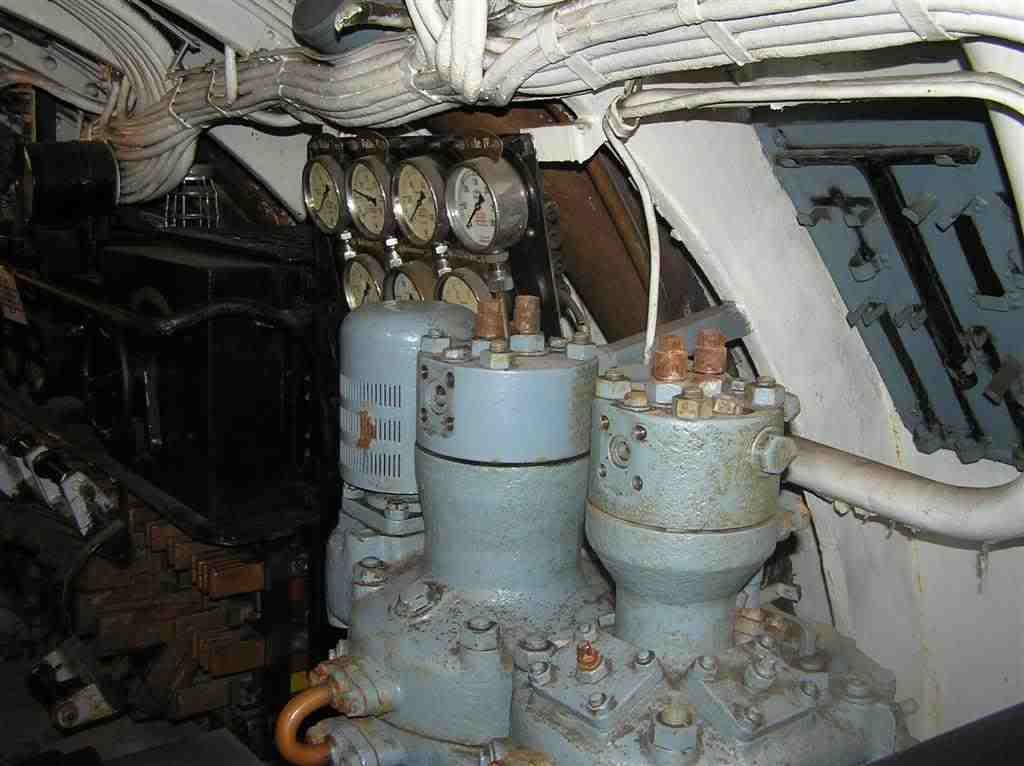 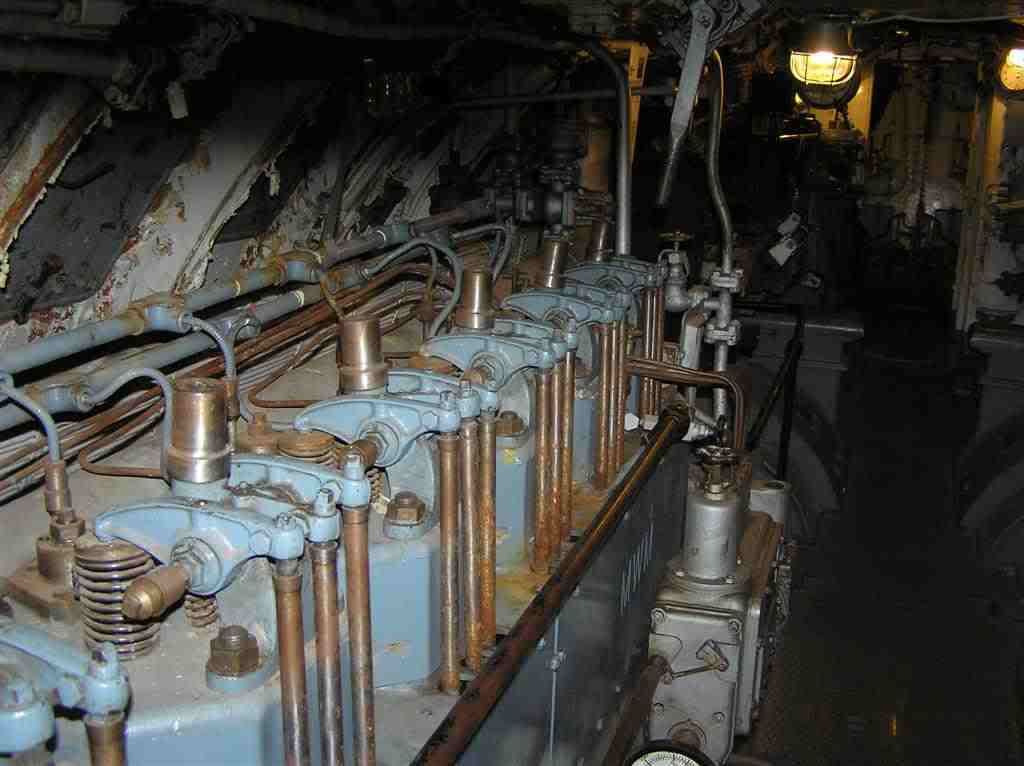
__________________
What we do in life echoes in Eternity |
|
|
|
|
01-04-09, 11:40 PM
|
#420 |
|
Watch
Join Date: May 2005
Posts: 21
Downloads: 41
Uploads: 0
|
Ooo, an interactive panoramic view of that sub's engine room. There are also the aft sleeping quarters and the "conning" tower.
http://www.360cities.net/image/wwii-...ne-engine-room Last edited by Buster_Dee; 01-04-09 at 11:58 PM. |
|
|
|
 |
|
|


 Linear Mode

