
|
|
SUBSIM: The Web's #1 resource for all submarine & naval simulations since 1997
|
SUBSIM: The Web's #1 resource for all submarine & naval simulations since 1997 |
|
|
 12-13-20, 06:06 PM
|
#1 |
|
Silent Hunter
  Join Date: Apr 2005
Posts: 4,705
Downloads: 300
Uploads: 0


|
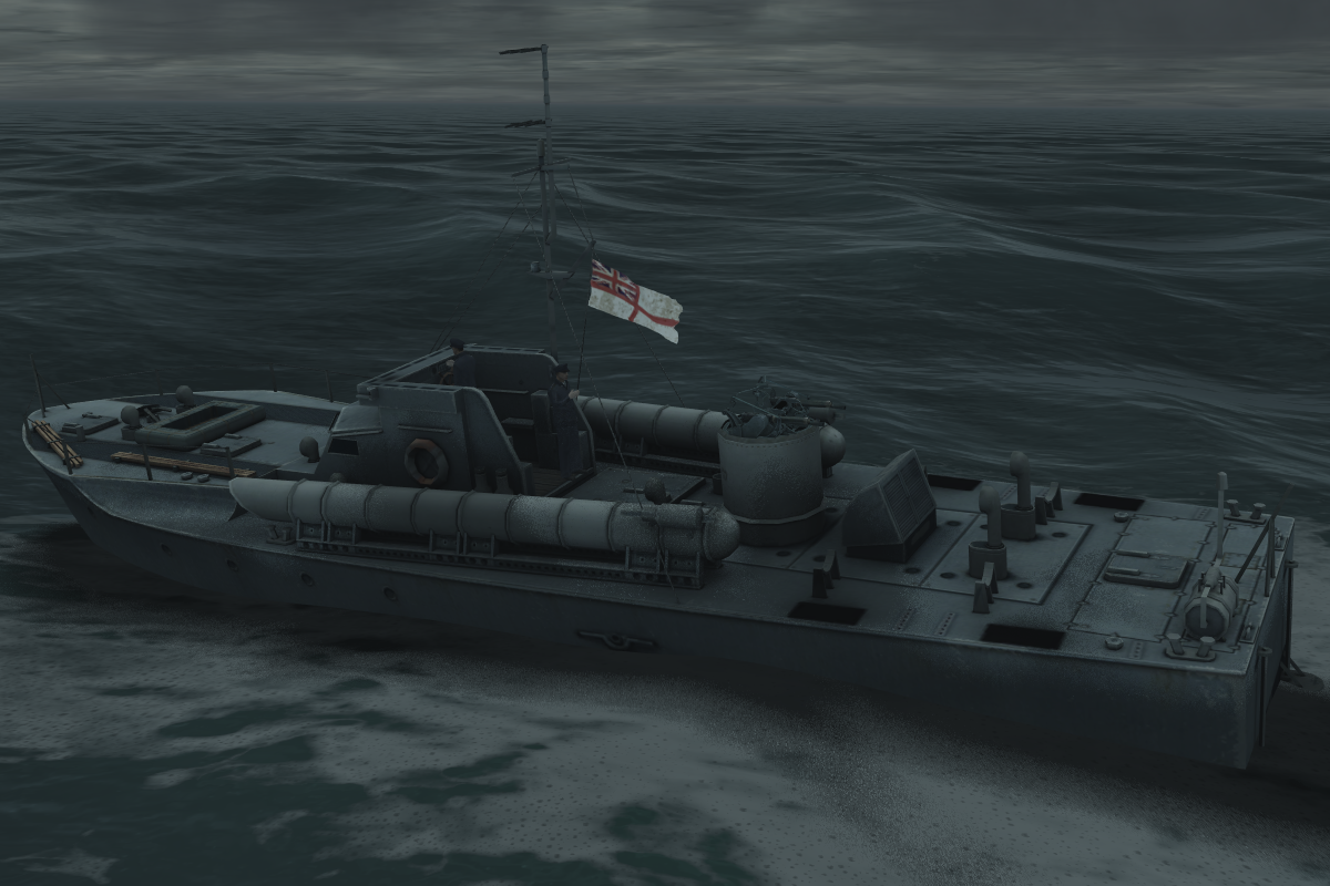
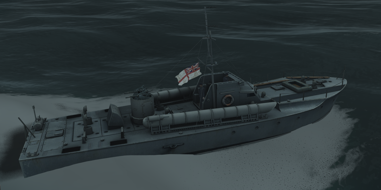
Great job! And nice to see another wings3d user active on the forums. The details are top notch, and the hull cross sections look correct.
In my opinion, small ships like these are needed much more than the big 5,000 - 10,000 tonners - even in WWII, little cargo vessels still made up a lot of the merchant fleet. And too often in SH3/4/5 we see big ships like Liberties operating inshore, where they rarely would have been in real life. Oh, and the accents in Sonarman's clip are great. 
|

|

|
|
12-13-20, 08:12 PM
|
#2 | ||||||||||
|
Navy Seal
 Join Date: Jan 2011
Location: CJ8937
Posts: 8,215
Downloads: 793
Uploads: 10
|
Quote:
Quote:
Quote:
Quote:
 Quote:
 Quote:
 Out of jokes: let's share our resources and discuss our respective projects. I am sure we can find some common priorities and if more cargo ships are part of those priorities, I will do my part of the job  Quote:
 Quote:
 Quote:
Talking about small details, I have a small problem that maybe you or kapuhy can help me with. From the plan I have used as template, and from several pictures I have seen, it seems that puffers had most of their rudder chain running in the open all the way from boat's wheel to the stern. As you can see from the screenshot below, the chain was not running straight but it formed several angles. I have tried modelling it as an almost flat geometry with a transparent, seamless chain texture. This is a trick I used for keeping acceptably low the poly count of other models, but in this case it didn't work. Due to the prominent position of that chain on to its changes of orientation, having it as a 2D texture looks really odd.  For the moment I have opted for a 3D chain. I simplified each chain link as much as possible; it is composed of just 18 vertices and 36 triangles, but there are many of those links, and in total the chain accounts for 2,232 vertices and 4,464 faces. A bit too much for a small detail like that. Do you guys have any better idea on how I could make that chain to look nice and natural while keeping its poly count under decent limits? Yes, I know, I could scrap it all, and very few naval fans would notice its absence, but being stubborn realism fanatic that I am, I can resolve to adopt such a drastic solution  Quote:
|
||||||||||
|
|
|
|
12-14-20, 01:14 PM
|
#3 | |
|
Grey Wolf
 Join Date: Oct 2010
Location: Poland
Posts: 874
Downloads: 72
Uploads: 3
|
Quote:
 Other than that, only thing I could think of is leave hanging part of chain as 3D and make the part that is running in the narrow "trench" 2d. EDIT: Or, make links a bit larger than they should be - not totally realistic but hardly noticeable and it will allow you to cover the distance with fewer links. Also, make sure parts of chain that are not visible (mainly concerning the "trench" part) are removed. In general, when I was modeling my ships I still didn't know if I will be able to import them as .gr2, so I set the polycount of Taihosan (nice looking .dat ship of circa 15k polys) as "alarm limit" - if any of my ships was reaching that, I'd start to cut details without mercy. Now with gr2 you have LOD model for larger distances so you can afford some more details. According to vdr1981, PB4Y plane model (160k triangles, aka two Queen Mary's) doesn't cause significant lag so the engine apparently can take it. |
|
|
|
|
|
12-14-20, 02:00 PM
|
#4 |
|
GLOBAL MODDING TERRORIST

Join Date: Sep 2014
Posts: 5,649
Downloads: 137
Uploads: 0

|
Back sides of the chain links will never be seen. Delete them.
Camera position in Game will not allow a close enough view to see most of it anyway. Is this to be a GR2 or dat version? |
|
|
|
|
12-14-20, 09:15 PM
|
#5 |
|
Navy Seal
Join Date: Jan 2011
Location: CJ8937
Posts: 8,215
Downloads: 793
Uploads: 10
|
Thank you for your good suggestions Maciej and Jeff
I had not considered "squaring" chain links. Indeed that would enable the saving of 12 triangles per link - 1,488 in total. In terms of aesthetics, I find "pointy" links preferable but that's such a small detail that at the end I might decide to use this trick. Modelling the lesser visible portions of that chain as 2D objects is an idea I had in mind, probably the best option in terms of poly reduction, but I need to check whether the transition between 2D and 3D links will be too evident. Removing "back sides" is another idea I had. It might be used on more enclosed portions of the chain as a lesser drastic alternative than making them flat and mapping a simple chain texture on them, but selecting the right faces to be deleted, might be a long and tedious task. @ Jeff For now my plan is to import the Lochinvar in game as a GR2 unit, but I don't exclude a later port to the dat format, for SHIII fans to enjoy her too. Such a conversion might bring some pro's, one of them being that we might bind the same link mesh to multiple nodes with different rotation/position settings. Again, the implementation of this elegant solution would involve some work, but it would be definitely worth all the effort. Unfortunately multiple bone bindings are not managed by the granny format (or by GR2 Editor) as well as by the dat format and S3d. Another fine solution for exploiting the 'multiple mesh usage' trick might be importing the chain as a separate dat object and linking it to the main GR2 unit via eqp file or merge controller. It wouldn't cast any dynamic shadows, but probably those shadows wouldn't be very noticeable anyway ______ Changing completely of topic I have a new question guys. If memory serves, torpedoes, bombs and guns shells make actual 3D holes on GR2 units that one can see through. Should I model some basic interiors for the upcoming unit? Last edited by gap; 12-14-20 at 09:28 PM. |
|
|
|
|
12-15-20, 12:38 AM
|
#6 | |
|
Loader
 Join Date: Nov 2012
Location: Russia
Posts: 83
Downloads: 72
Uploads: 1
|
Greetings, gap, and glad to see you.
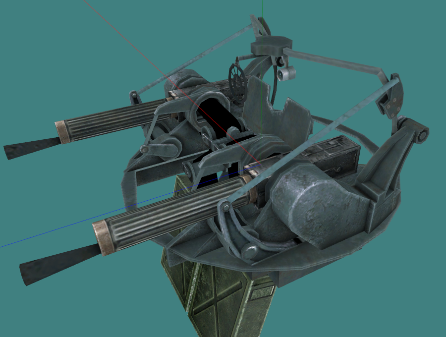
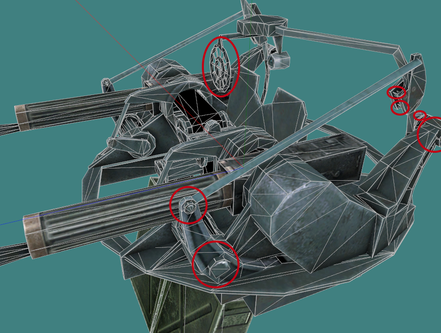
I think you absolutely should not bother about this little thing-a chain in 3D execution. (You can make a solid long object with a simple cross-section, and make details-chain links using a texture). And i will give you an example, i think very suitable, which should convince you of this. Here is the “Vickers mgun Mk-5 mount” that I was started to make for a Torpedo boat for SH5, the old one, in SH4 that was too rough and simple, I wanted to make it more detailed. In addition, I had to try to adjust the geometry of the game model and its moving parts, the movement of which is simplified under the conditions of the game and based only on the rotation base and traverse of barrel blocks, so that it was most similar to the original and did not cause visual dissonance, because this turret in reality has a rather complex design and motor skills with many moving parts and the movement of articulated structures.. perhaps this adjustment was excessive, because all this turned out to be again inconspicuous in the game. This is the final view, but before its start assembling it in GR2 and texturing it, it went through the maximum simplification and initially had even more details. But as I later saw the result in the game, the model could be safely-simplified cut back, for example, in these details: and this is without prejudice to her appearance.. these MachineGun parts are too small. Well. These are the closest screenshots in the game that I managed to make (with a resolution of 1920x1080): Even in optics from a distance of 150-200 m from the submarine details are indistinguishable: As I did not try to make out the pins of the hinges and other small details-in the game they were indistinguishable and invisible. The length of your ship (66 ft) length - 20.08 m, the dimensions of Vosper (70-72 ft) length - 22.1 m. Approximately comparable. Look at Vosper and look at Vickers, then look at your ship and the chain – it will be a barely discernible "thread" in the game render. Do you need it made entirely in 3D, the beauty of which can be seen and appreciated only in the exported model in a 3D editor or viewer? The weight of the entire final Vickers model cost 4070 faces, I think it could be safely reduced to 4000 without losing the visual, having the experience gained. This is a whole anti-aircraft mount that can be reused, for example, on some fairmile-d or others. similar to vosper*s if our develop the mtb shipyard in the game. You have one chain… In general, the choice is yours, gap. ***** In addition, you can use such details as: a slightly convex door and the contours of the eluminators – you can simply bake them into a high-quality Normal map and Diffuse and remove the 3D details. ***** Quote:
And in SH4 " holes” - yes - there is a sense to do the internal content, but the "holes" against the background of such small ships (although, i think, here you need to consider each ship separately, depending on different details: whether there are high large superstructures and how the frame models themselves look, etc. - perhaps in some cases 3d internal frames will look normal when damaged), as far as I remember, were so big that it is better without them, and I did not connect these damages on Vosper in SH-IV. And of course: all of the above is just my opinion. 
Last edited by Rosomaha; 12-15-20 at 12:46 AM. |
|
|
|
|
|
12-15-20, 03:32 AM
|
#7 | ||
|
Grey Wolf
Join Date: Oct 2010
Location: Poland
Posts: 874
Downloads: 72
Uploads: 3
|
Quote:
Quote:
On another note and related to earlier posts about sharing resources and plans - there seem to be several units currently in progress, perhaps (just a thought) we might use a sticky thread in SH5 Mods Workshop somewhat like this: https://www.subsim.com/radioroom/showthread.php?t=97328 Such thread would contain list of WIP units currently being made and perhaps links to resources like plans or models available online in case a newcomer would like to give a try to creating a new unit. Plus, maybe some form of basic guide for importing units as the needed info is currently spread over many multi-page threads. Last edited by kapuhy; 12-15-20 at 03:45 AM. |
||
|
|
|
|
03-03-21, 04:05 PM
|
#8 | ||
|
Navy Seal
Join Date: Jan 2011
Location: CJ8937
Posts: 8,215
Downloads: 793
Uploads: 10
|
Quote:
Yes, davit's arc could have been smoother. The same goes for vent's inner part and for many other small details, if you look at them from close enough. At some point one needs to put the word "end" to his projects, and this is the case with my puffer as long as the 3D modelling job is concerned. In future someone else might bring his own improvements to it, and I will be glad to accept them, but by then I hope I will be working on something else  Quote:
1 - The screenshots I posted yesterday were taken in Wings3D. Wings is not a 3D rendering program, so don't expect too much from it. It supports the creation of scenes with various types of lights, but I never messed with them. The one source of light in my screeshots is a standard emispherical lighting which, I think, is aligned with the x axis. That's why one side of the boat looks more illuminated than the other. 2 - For the above reasons, my previews don't feature any dynamic shadow. If you compare the pictures at post #46 with the one at post #1 you will easily realize that, in the screenshots I posted more recently, the shadowing comes mostly from the ambient occlusion map. Considering that, it is logical for objects on the deck - whose exposure to diffuse light is occluded by bulwarks and superstructure - to be darker than hull. In game, this will be balanced by direct sunlight beams and by the dynamic shadows supported by the granny format. 3 - The program I used for AO-map baking is Autodesk Softimage Mod Tool 7.5. This is the free version of the program devs used for the same job in SHIV and SH5. The only manual touch ups I made to the procedural AO map, was subduing by 50% or removing the pre-rendered diffuse shadows cast by breakable model parts, otherwise those darker spots would look odd when the boat is damaged and the objects casting them are ripped away from the main model. |
||
|
|
|
|
03-04-21, 04:37 AM
|
#9 | |||
|
Grey Wolf
Join Date: Feb 2021
Posts: 923
Downloads: 27
Uploads: 0

|
Quote:
2) Can't you have any preview directly in Autodesk Softimage Mod Tool 7.5 ? Quote:
Quote:
5) Other than that, one quick question : what is the sail used for, as there is already a propeller ? I doubt that it's used for propulsion purpose. Maybe for lateral maneuvers ? 
Last edited by Mister_M; 03-04-21 at 04:51 AM. |
|||
|
|
|
|
03-04-21, 05:43 AM
|
#10 | |
|
Grey Wolf
Join Date: Oct 2010
Location: Poland
Posts: 874
Downloads: 72
Uploads: 3
|
Quote:
|
|
|
|
|
|
03-04-21, 07:09 AM
|
#11 | |
|
Grey Wolf
Join Date: Feb 2021
Posts: 923
Downloads: 27
Uploads: 0
|
Quote:
But also, I see that this sail has a fixed position and it can't be oriented (only a little by fixing the "flying" cable) to one side or the other, so not very useful to navigate... Edit : I couldn't find any picture of a Clyde puffer with a sail. It was then probably used only in extreme emergency situations... Last edited by Mister_M; 03-04-21 at 07:40 AM. |
|
|
|
|
|
03-04-21, 11:42 AM
|
#12 | |||||
|
Navy Seal
Join Date: Jan 2011
Location: CJ8937
Posts: 8,215
Downloads: 793
Uploads: 10
|
Quote:
1 - The AO map contains pre-rendered shadows; think of it as the soft shadows cast by diffuse light. 2 - Surface normals are another important factor which determines the luminosity of a surface; the more parallel a normal is to the direction of incident light, the lighter will be the relative surface. 3 - Normals are also affected by object smoothing; this is the hardness of the edges connecting the triangles that compose a curved surface. By default, edges are considered "soft". That means that the normal of each triangle is averaged with the normals of neighbouring triangles, giving the surface a smooth look with subtle changes of luminosity. Nonetheless, edges can be set to "hard", which means that there will be an abrupt change of luminosity between a triangle and the next ones, and that the edges between adjoining triangles will be well noticeable if their normals point to radically different directions. 4 - Finally we have dynamic shadows: the sharp shadows cast on top of an object when another object is blocking light rays for it. Off the four factors I summarized above, the effect of the last three is subject to quantity and direction of a directional light source (such as the sun), whereas the the first one is static and it is supposed to simulate ambient (i.e. diffuse) light. In my last previews, you can see the effect of the first three of them but, as I wrote yesterday, the illumination I set in Wings3D was actually a diffuse light coming from one side (like the sun light at dusk). In game, a variety of different illuminations will apply depending on time season, time of the day and weather. Quote:
Quote:
Quote:
Quote:
The plan that this model is based on also features a mainsail, but that was used very rarely (probably in case of emergencies as noted by kapuhy) and I decided not to include it in my model. Last edited by gap; 03-04-21 at 11:58 AM. |
|||||
|
|
|
|
03-04-21, 12:19 PM
|
#13 | |||
|
Grey Wolf
Join Date: Feb 2021
Posts: 923
Downloads: 27
Uploads: 0
|
Thank you for your very detailed, patient and clear explanations. I'm impressed, and happy to learn so many things !
I still have a few comments : Quote:
Quote:
Quote:
Last edited by Mister_M; 03-04-21 at 12:36 PM. |
|||
|
|
|
|
03-04-21, 04:40 AM
|
#14 |
|
Grey Wolf
Join Date: Feb 2021
Posts: 923
Downloads: 27
Uploads: 0
|
sorry, duplicated post.....
|
|
|
|
 |
|
|


 Hybrid Mode
