SUBSIM Radio Room Forums


SUBSIM: The Web's #1 resource for all submarine & naval simulations since 1997

Go Back   SUBSIM Radio Room Forums > Silent Hunter 3 - 4 - 5 > Silent Hunter 4: Wolves of the Pacific
Forget password? Reset here

Reply
 
Thread Tools Display Modes
Old 09-08-15, 07:51 PM   #46
TorpX
Silent Hunter
 
Join Date: Sep 2010
Posts: 3,975
Downloads: 153
Uploads: 11
Default

Quote:
Originally Posted by snakedocpl View Post
I think, that is by design. The Angle Solver of the US TDC is driven by Position Keeper. I mean, that Angle Solver calculates final solution based on the target parameters calculated by Position Keeper (which is modelling the relative position between the target and own ship). After inputting some initial values into Position Keeper, it constantly updates the position of the target relative to the own boat. There are some outputs (for instance GENERATED BEARING), which are used to verify, if assumed initial values were correct. So they read GENERATED BEARING, set the TBT or periscope at this bearing and then - if the target was there - that meant, that model is correct. If not - the initial target parameters were wrong.
Yes, I see your point. I kind of forgot about that aspect of the operation.


TorpX is offline   Reply With Quote
Old 09-09-15, 09:44 AM   #47
CapnScurvy
Admiral
 
CapnScurvy's Avatar
 
Join Date: Apr 2005
Location: Dayton, Ohio
Posts: 2,292
Downloads: 474
Uploads: 64


Default

Quote:
Originally Posted by BigWalleye View Post
Cap'n Scurvy has a periscope photo of the stabilized azimuth line and a description of how it was used in Post #26 of this thread.
Hi BigWalleye, that photo you mentioned is not looking through a periscope. It's looking through one of the eye pieces of a TBT (that's the Nautilus conning tower in the background).


I forget which side it was, but the stationary lines within the one lens is what you're looking at.


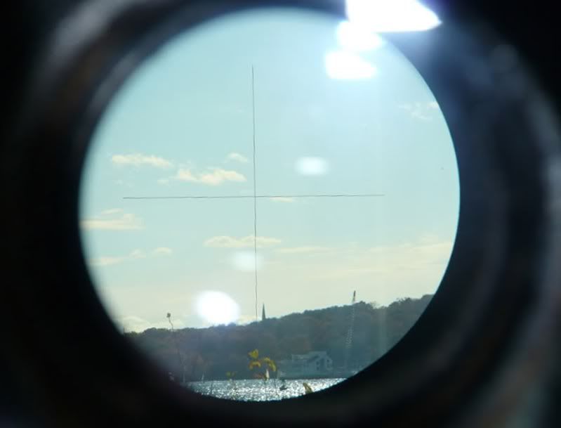
I don't have a picture of what the Stabilize Azimuth Line would have looked like within the Kollmorgen Periscope. Guess it was just a vertical line, separate of the Telemeter Divisions within the lens.
__________________


The HMS Shannon vs. USS Chesapeake outside Boston Harbor June 1, 1813

USS Chesapeake Captain James Lawrence lay mortally wounded...
Quote:
.."tell the men to fire faster, fight 'till she sinks,..boys don't give up the ship!"
CapnScurvy is offline   Reply With Quote
Old 09-09-15, 03:14 PM   #48
ColonelSandersLite
Captain
 
Join Date: Aug 2009
Posts: 481
Downloads: 74
Uploads: 3
Default

From the instructions on the thing, I get the impression that it is a pretty fat line too. If it was as thin as the regular lines on the optics, using one side of the line as reference would probably be a non issue in practicality I think.

I'm also pretty sure it wasn't holographic from the description. It was probably literally a plain black metal bar that would move across the periscopes eyepiece at a rate determined by the gyrocompass, periscope bearing, and submarine speed.
__________________
My SH4 LP
ColonelSandersLite is offline   Reply With Quote
Old 09-10-15, 07:32 AM   #49
snakedocpl
Swabbie
 
Join Date: Jan 2011
Posts: 12
Downloads: 21
Uploads: 0
Default

Quote:
Originally Posted by TorpX View Post
Quote:
Originally Posted by snakedocpl View Post
I think, that is by design. The Angle Solver of the US TDC is driven by Position Keeper. I mean, that Angle Solver calculates final solution based on the target parameters calculated by Position Keeper (which is modelling the relative position between the target and own ship). After inputting some initial values into Position Keeper, it constantly updates the position of the target relative to the own boat. There are some outputs (for instance GENERATED BEARING), which are used to verify, if assumed initial values were correct. So they read GENERATED BEARING, set the TBT or periscope at this bearing and then - if the target was there - that meant, that model is correct. If not - the initial target parameters were wrong.
Yes, I see your point. I kind of forgot about that aspect of the operation.
Please note, that US TDC made possible to launch torpedoes without using periscope. If the target course parameters for the Position Keeper were correct and target moved on steady course, the Commander did not have to look through the periscope to aim the torpedoes. In reality, just before launch, the Commander looked through the scope to make sure, that target is there, where it should be.
Quote:
Originally Posted by BigWalleye View Post
Cap'n Scurvy has a periscope photo of the stabilized azimuth line and a description of how it was used in Post #26 of this thread.
The stabilized line in space was also present in the German periscopes manufacted by Zeiss. They called it "Feste Linie im Raum". As far as I know, the WWII U-Boats were not fitted with periscopes with this feature.

Quote:
Originally Posted by ColonelSandersLite View Post
From the instructions on the thing, I get the impression that it is a pretty fat line too. If it was as thin as the regular lines on the optics, using one side of the line as reference would probably be a non issue in practicality I think.

I'm also pretty sure it wasn't holographic from the description. It was probably literally a plain black metal bar that would move across the periscopes eyepiece at a rate determined by the gyrocompass, periscope bearing, and submarine speed.
Well, looking at the drawing at the end of the manual (http://www.maritime.org/doc/pdf/peri...type2-1940.pdf), it seems, that it is quite fat line. I have attached the drawing with essential elements marked:


I think, that in the view field, this line looked as on images below:


On the first image, the line was positioned at the bow of the (stationary) ship. On the second image, the periscope was moved to the left.

Quote:
Originally Posted by CapnScurvy View Post
Hi BigWalleye, that photo you mentioned is not looking through a periscope. It's looking through one of the eye pieces of a TBT (that's the Nautilus conning tower in the background).

I forget which side it was, but the stationary lines within the one lens is what you're looking at.
Looking at this manual (http://www.maritime.org/doc/pdf/tbt.pdf), it seems, that TBT was not fitted in "stabilized line in space".

Quote:
Originally Posted by ColonelSandersLite View Post
I'm also pretty sure it wasn't holographic from the description. It was probably literally a plain black metal bar that would move across the periscopes eyepiece at a rate determined by the gyrocompass, periscope bearing, and submarine speed.
The stabilized line compensated only change of periscope bearing and change of submarine course. It could do nothing with the speed. To make the target speed most accurate, the speed of own submarine should be relatively small.

--
Regards
Maciek

snakedocpl is offline   Reply With Quote
Old 09-10-15, 08:39 AM   #50
CapnScurvy
Admiral
 
CapnScurvy's Avatar
 
Join Date: Apr 2005
Location: Dayton, Ohio
Posts: 2,292
Downloads: 474
Uploads: 64


Default

Snakedocpl, I believe your images of the Stabilized Azimuth Line are a bit misleading. The line could be placed anywhere within the periscopes Field of View. It was independent from the Telemeter Divisions........ so it was not "centered" to the FoV. You focused the line (bringing it in sharper), placing it just ahead of the targets bow, then turned the clutch "in" to engage the synchronous motor (which would have already been plugged in) just as the targets bow touched the line. Using a stop watch, you time the passage of the target. Unlike the images, there are no graduated marks, or scale for the Stabilized Line......just a line.

I'm not nit picking your help, just don't want to mislead anyone.

Quote:
Originally Posted by Snakedocpl
The stabilized line compensated only change of periscope bearing and change of submarine course. It could do nothing with the speed. To make the target speed most accurate, the speed of own submarine should be relatively small.
The estimated target Speed is calculated by knowing the estimated length of the target, and how long the target takes to pass the Stabilized Azimuth Line. That's why the stop watch is used. Estamated Speed was found.

Quote:
Originally Posted by Snakedocpl
Looking at this manual (http://www.maritime.org/doc/pdf/tbt.pdf), it seems, that TBT was not fitted in "stabilized line in space".
That's correct. The TBT has only the permanent "cross hairs" as shown. Which by the way were "illuminated" for night use.....when plugged in.
__________________


The HMS Shannon vs. USS Chesapeake outside Boston Harbor June 1, 1813

USS Chesapeake Captain James Lawrence lay mortally wounded...
Quote:
.."tell the men to fire faster, fight 'till she sinks,..boys don't give up the ship!"
CapnScurvy is offline   Reply With Quote
Old 09-10-15, 08:53 AM   #51
ColonelSandersLite
Captain
 
Join Date: Aug 2009
Posts: 481
Downloads: 74
Uploads: 3
Default

Quote:
Originally Posted by snakedocpl View Post
The stabilized line compensated only change of periscope bearing and change of submarine course. It could do nothing with the speed. To make the target speed most accurate, the speed of own submarine should be relatively small.
I'll go over the rest in more detail later, but I would like to know where you're getting that particular piece of information. It's possible that the stabilization mechanism assumed a standard tactical speed (like maybe 2 knots submerged or something). However, it does not say anywhere that I'm seeing that sub speed is not known to the unit. It does specifically say that it is getting data from the ships gyrocompass, which knows ships speed.


@scurvy
You're misreading him on that first quote. He's talking about sub speed, not target speed.
__________________
My SH4 LP
ColonelSandersLite is offline   Reply With Quote
Old 09-10-15, 09:08 AM   #52
CapnScurvy
Admiral
 
CapnScurvy's Avatar
 
Join Date: Apr 2005
Location: Dayton, Ohio
Posts: 2,292
Downloads: 474
Uploads: 64


Default

ColonelSandersLite........
__________________


The HMS Shannon vs. USS Chesapeake outside Boston Harbor June 1, 1813

USS Chesapeake Captain James Lawrence lay mortally wounded...
Quote:
.."tell the men to fire faster, fight 'till she sinks,..boys don't give up the ship!"
CapnScurvy is offline   Reply With Quote
Old 09-10-15, 09:22 AM   #53
snakedocpl
Swabbie
 
Join Date: Jan 2011
Posts: 12
Downloads: 21
Uploads: 0
Default

Quote:
Originally Posted by ColonelSandersLite View Post
I'll go over the rest in more detail later, but I would like to know where you're getting that particular piece of information. It's possible that the stabilization mechanism assumed a standard tactical speed (like maybe 2 knots submerged or something). However, it does not say anywhere that I'm seeing that sub speed is not known to the unit. It does specifically say that it is getting data from the ships gyrocompass, which knows ships speed.

How gyrocompass knows the ship speed? I have always thought, that it knows only its course. The speed is measured by log.
The periscope manual says:
Quote:
The azimuth line is actuated by a self synchronous motor, which in turn is governed by the gyro compass of the submarine. The position of the line is thus independent of changes in the course of the submarine, but if the periscope is rotated in its bearings the azimuth line will of course move against the field.
--
Regards
Maciek

Last edited by snakedocpl; 09-10-15 at 09:29 AM.
snakedocpl is offline   Reply With Quote
Old 09-10-15, 09:29 AM   #54
snakedocpl
Swabbie
 
Join Date: Jan 2011
Posts: 12
Downloads: 21
Uploads: 0
Default

Quote:
Originally Posted by CapnScurvy View Post
Snakedocpl, I believe your images of the Stabilized Azimuth Line are a bit misleading. The line could be placed anywhere within the periscopes Field of View. It was independent from the Telemeter Divisions........ so it was not "centered" to the FoV. You focused the line (bringing it in sharper), placing it just ahead of the targets bow, then turned the clutch "in" to engage the synchronous motor (which would have already been plugged in) just as the targets bow touched the line. Using a stop watch, you time the passage of the target. Unlike the images, there are no graduated marks, or scale for the Stabilized Line......just a line.
These images are my impression, because I have never look through the periscope with stabilized line. The impression based on the construction drawing of the ocular box. I marked stabilized line with red color. Of course it can be moved through the view (after decoupling from motor). The first drawing presents it after placing it at the bow of the target. On the second drawing the scope was rotated, but line stays at the same place as before (rotated by synchro-motor). That's why I wrote, that target is stationary. In reality, the target would move, and the line would be slightly shifted relative to the bow.

--
Regards
Maciek

Last edited by snakedocpl; 09-10-15 at 09:36 AM.
snakedocpl is offline   Reply With Quote
Old 09-10-15, 09:34 AM   #55
ColonelSandersLite
Captain
 
Join Date: Aug 2009
Posts: 481
Downloads: 74
Uploads: 3
Default

The gyrocompass needs to know ship speed in order to compensate for latitude & speed error. For the basic theory, see page 10 of the gyrocompass manual here: http://www.maritime.org/doc/gyromk7/index.htm

So yeah, the periscope is connected to the ships gyrocompass, which gets speed from the underwater log.
__________________
My SH4 LP
ColonelSandersLite is offline   Reply With Quote
Old 09-10-15, 09:47 AM   #56
snakedocpl
Swabbie
 
Join Date: Jan 2011
Posts: 12
Downloads: 21
Uploads: 0
Default

Quote:
Originally Posted by ColonelSandersLite View Post
The gyrocompass needs to know ship speed in order to compensate for latitude & speed error. For the basic theory, see page 10 of the gyrocompass manual here: http://www.maritime.org/doc/gyromk7/index.htm

So yeah, the periscope is connected to the ships gyrocompass, which gets speed from the underwater log.
Well, you are right, the speed is used to get the corrected course. But all the gyro repeaters (driven by gyro compass) receives only course. At the end of the periscope manual you have wiring of the plug and socket. You can see there two power lines (R1 and R2)and three phase lines (S1, S2, S3).
Here you have got wiring of the repeaters:
http://www.maritime.org/doc/gyromk7/part2.htm#pg72
There is no way to transmit speed, only the course.

--
Regards
Maciek
snakedocpl is offline   Reply With Quote
Old 09-11-15, 06:08 AM   #57
ColonelSandersLite
Captain
 
Join Date: Aug 2009
Posts: 481
Downloads: 74
Uploads: 3
Default

Good catch, you're certainly right on that. The stabilization must have used an assumed submarine speed. Whether it was 0 knots or some other number, I see no indication of. I sort of doubt it was 0 as if this is the case, the entire system is sorta pointless as you could just use the centerline of the periscope instead.


It seems that the 89KA40/1.414 was replaced by the 91KA40T/1.414HA sometime during the war. Looking at the maintenance manual for the new model, I notice that the stabilized azimuth line function is completely omitted. No mention as to why, but I would think it was either regarded as mechanically unreliable or just not useful. That might (or just as easily might not) tie into the above uselessness of a stabilized line that does not in any way account for submarine speed.


I'm not sure when exactly these replacements where made but looking at a few periscopes in surviving boats (no, I didn't check them all, just a few) the ones I saw where all the 91. I had been thinking that maybe the groups in charge of one of the surviving boats would be willing to provide a picture but I suspect that there are probably no surviving model 89s left.


As an aside, it seems the "observation scope" at the start of the war was 88KA40/1.99 (a type III). Replaced by the 92KA40T/1.99 (also type III) and then the 93KN36 (type IV). Again, dates are something I don't have.

Type I - Obsolete (S Boat scopes maybe? No information)
Type II - Attack Scope
Type III - General Purpose
Type IV - Night Scope
__________________
My SH4 LP

Last edited by ColonelSandersLite; 09-11-15 at 06:32 AM.
ColonelSandersLite is offline   Reply With Quote
Old 09-11-15, 10:10 AM   #58
CapnScurvy
Admiral
 
CapnScurvy's Avatar
 
Join Date: Apr 2005
Location: Dayton, Ohio
Posts: 2,292
Downloads: 474
Uploads: 64


Default

I've come to the same conclusion Colonel.

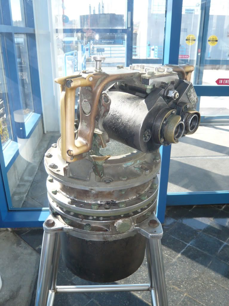
The earlier Kollmorgen periscope model had the Stabilized Azimuth Line, the 91KA40T did not. It stands to reason why there's no reference to using the Stabilized Line in the 1952 Submarine Torpedo Fire Control Manual. Also, I could find no periscope images of the Line in use.

I did find an image that I couldn't resist to show :


__________________


The HMS Shannon vs. USS Chesapeake outside Boston Harbor June 1, 1813

USS Chesapeake Captain James Lawrence lay mortally wounded...
Quote:
.."tell the men to fire faster, fight 'till she sinks,..boys don't give up the ship!"
CapnScurvy is offline   Reply With Quote
Old 09-11-15, 11:29 AM   #59
snakedocpl
Swabbie
 
Join Date: Jan 2011
Posts: 12
Downloads: 21
Uploads: 0
Default

Quote:
Originally Posted by ColonelSandersLite View Post
Good catch, you're certainly right on that. The stabilization must have used an assumed submarine speed. Whether it was 0 knots or some other number, I see no indication of. I sort of doubt it was 0 as if this is the case, the entire system is sorta pointless as you could just use the centerline of the periscope instead.


It seems that the 89KA40/1.414 was replaced by the 91KA40T/1.414HA sometime during the war. Looking at the maintenance manual for the new model, I notice that the stabilized azimuth line function is completely omitted. No mention as to why, but I would think it was either regarded as mechanically unreliable or just not useful. That might (or just as easily might not) tie into the above uselessness of a stabilized line that does not in any way account for submarine speed.


I'm not sure when exactly these replacements where made but looking at a few periscopes in surviving boats (no, I didn't check them all, just a few) the ones I saw where all the 91. I had been thinking that maybe the groups in charge of one of the surviving boats would be willing to provide a picture but I suspect that there are probably no surviving model 89s left.

Well, I think the same. Taking into account correction for own speed would require the knowledge of the target AoB and target bearing (you don't need correction if the target is just ahead, but you need if it is abeam). All this would require small calculating device. I think, that such device was not developed because it would be complicated, its input depended on estimated value of AoB, so it would not give any advantage over plotting or even estimating. I suppose, stabilized line was abandoned because it just impractical. The absence of such device in U-Boats periscopes (despite the fact that Zeiss manufactured periscopes with "Feste Linie im Raum") would confirm such assumption.

--
Regards
Maciek
snakedocpl is offline   Reply With Quote
Old 09-12-15, 12:54 AM   #60
TorpX
Silent Hunter
 
Join Date: Sep 2010
Posts: 3,975
Downloads: 153
Uploads: 11
Default

Quote:
Originally Posted by snakedocpl View Post
Well, I think the same. Taking into account correction for own speed would require the knowledge of the target AoB and target bearing (you don't need correction if the target is just ahead, but you need if it is abeam).
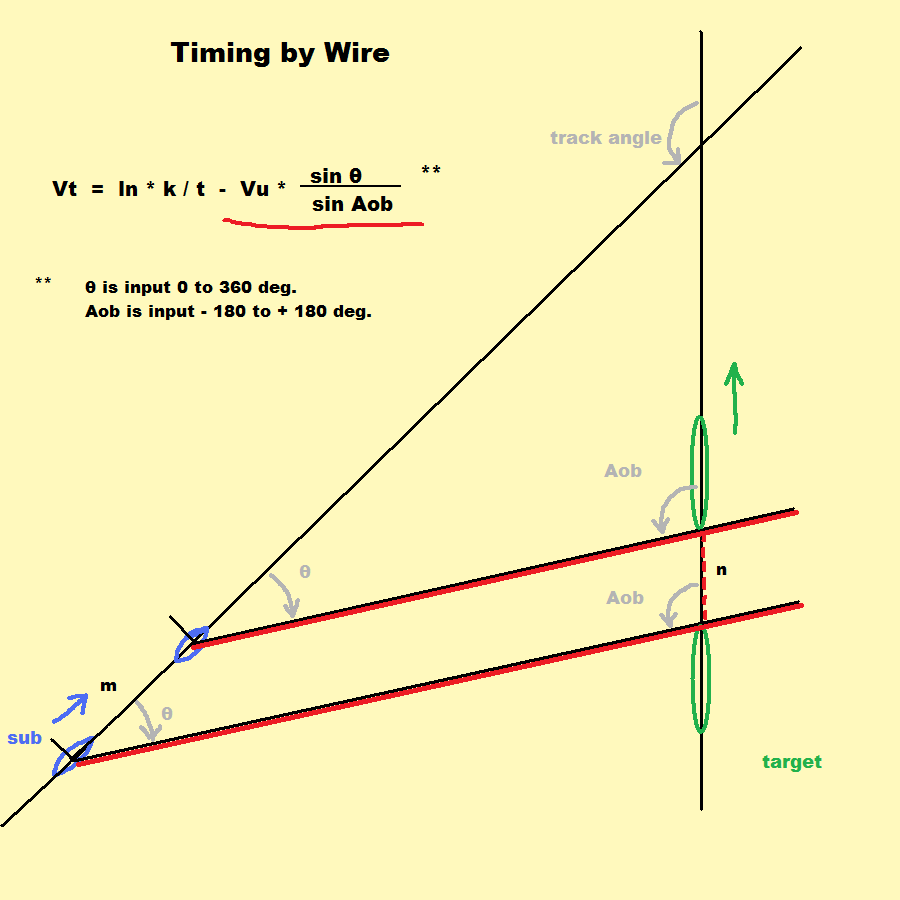
Actually, you don't necessarily need the target Aob.


Below, is a geometric solution for timing by wire that doesn't make use of any "stabilized line", or special equipment. In this solution, you do need to know the Aob, and of course, target bearing, and sub speed.

The 'line' moves with the sub, but the angle doesn't change.

The underlined term in the formula accounts for the movement of the line and the space along the target track marked by 'n'.


However, if you had a mechanism to move or "stabilize" the line, there are other possibilities. Below is a diagram illustrating what a solution might look like with the line being moved. This simplifies the calculation of target speed in that the underlined term in the first formula is eliminated.


Note that for the mechanism to know how fast the line is to be moved, the range has to be known.

The initial rate of change of angle a =

(Vu*k sin a) / (2*pi*Range) * (360*60)

I computed an example for a sub moving at 3 kn., timing a target at 2,000 yds., at 45°.

(3*0.563*sin 45) / (2*pi*2000) * (360 * 60) = 2.05° per minute

The problem with the above is that the rate of change of the angle is not constant, so it would have to be dynamically calculated by the TDC, or some mechanism. Of course, the calculation is no more complicated than the other quantities the TDC calculates, so it is certainly possible.

Without some kind of mechanism to calculate the above, I don't really see any point in the technology.

I suspect the reason the feature was not carried over, was that it was rendered unnecessary by RADAR. With a RADAR plot, the target speed could be accurately determined without identification, or knowing the ship's length.


TorpX is offline   Reply With Quote
Reply


Posting Rules
You may not post new threads
You may not post replies
You may not post attachments
You may not edit your posts

BB code is On
Smilies are On
[IMG] code is On
HTML code is Off

Forum Jump


All times are GMT -5. The time now is 09:08 AM.


Powered by vBulletin® Version 3.8.11
Copyright ©2000 - 2025, Jelsoft Enterprises Ltd.
Copyright © 1995- 2025 Subsim®
"Subsim" is a registered trademark, all rights reserved.