
|
|
SUBSIM: The Web's #1 resource for all submarine & naval simulations since 1997
|
SUBSIM: The Web's #1 resource for all submarine & naval simulations since 1997 |
|
|
 08-08-16, 12:05 PM
|
#1 | |
|
GLOBAL MODDING TERRORIST

Join Date: Sep 2014
Posts: 5,654
Downloads: 137
Uploads: 0


|
Quote:
He's starting to over whelm the old one!  OK. 10 days in the brig?  
|
|

|

|
|
08-08-16, 12:25 PM
|
#2 | |
|
Eternal Patrol

 Join Date: Nov 2002
Location: High in the mountains of Utah
Posts: 50,369
Downloads: 745
Uploads: 249


|
Quote:
__________________
Never do anything you can't take back. Rocky Russo |
|
|
|
|
|
08-08-16, 01:09 PM
|
#3 | |
|
GLOBAL MODDING TERRORIST
Join Date: Sep 2014
Posts: 5,654
Downloads: 137
Uploads: 0
|
Quote:
|
|
|
|
|
|
08-08-16, 01:12 PM
|
#4 | |
|
GLOBAL MODDING TERRORIST
Join Date: Sep 2014
Posts: 5,654
Downloads: 137
Uploads: 0
|
Quote:
I do have to say Neal is ageing much better then Mel. 
|
|
|
|
|
|
08-08-16, 02:08 PM
|
#5 |
|
Dipped Squirrel Operative

 Join Date: Sep 2001
Location: ..where the ocean meets the sky
Posts: 17,773
Downloads: 38
Uploads: 0
|
Hello again,
some more photos, the rest can be viewed or downloaded via the dropbox link at the end. Once more the observation perisope down in the control room, we were wondering why there are two oculars.. anyone?  The "Weihnachtsbaum", or christmas tree. The black shaft at the left turns the antenna, when extended.  Engine compartment with view aft, intake and exhaust valves above:  Switching table for the starboard electric engine:  All other photos i made are here: https://www.dropbox.com/sh/4sra8zknp...Lh2jLqzza?dl=0 Best wishes, Catfish
__________________
 >^..^<*)))>{ All generalizations are wrong. Last edited by Catfish; 08-08-16 at 02:18 PM. |
|
|
|
|
08-08-16, 03:23 PM
|
#6 |
|
Born to Run Silent

Join Date: Jan 1997
Location: Cougar Trap, Texas
Posts: 21,385
Downloads: 541
Uploads: 224
|
Cathfish!
__________________
SUBSIM - 26 Years on the Web |
|
|
|
|
08-08-16, 03:33 PM
|
#7 |
|
Dipped Squirrel Operative
Join Date: Sep 2001
Location: ..where the ocean meets the sky
Posts: 17,773
Downloads: 38
Uploads: 0
|
^ I knew i forgot to delete something
__________________
>^..^<*)))>{ All generalizations are wrong. |
|
|
|
|
08-08-16, 03:40 PM
|
#8 | |
|
Chief of the Boat

Join Date: Feb 2006
Location: 250 metres below the surface
Posts: 190,645
Downloads: 63
Uploads: 13


|
Quote:
__________________
Wise men speak because they have something to say; Fools because they have to say something.
Oh my God, not again!!  |
|
|
|
|
|
08-08-16, 05:21 PM
|
#9 | ||
|
Gefallen Engel U-666

Join Date: Jul 2013
Location: On a tilted, overheated, overpopulated spinning mudball on Collision course with Andromeda Galaxy
Posts: 30,031
Downloads: 24
Uploads: 0

|
Quote:
Quote:
Backside view 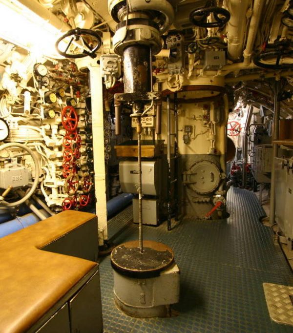 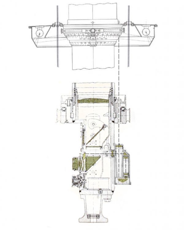 The cross-section of the type NLSR C/9 periscope ocular box (the optical system for transmitting bearing scale is visible) The cross-section of the type NLSR C/9 periscope ocular box (the optical system for transmitting bearing scale is visible)
__________________
"Only two things are infinite; The Universe and human squirrelyness?!! Last edited by Aktungbby; 08-09-16 at 12:48 AM. |
||
|
|
|
|
08-08-16, 06:02 PM
|
#10 |
|
Starte das Auto

Join Date: Aug 2014
Location: The Fens
Posts: 17,408
Downloads: 5
Uploads: 0

|
This is the best thread... wish I'd been there too
 (and Schroeder) (and Schroeder)
__________________

|
|
|
|
|
08-09-16, 04:12 AM
|
#11 | |
|
Dipped Squirrel Operative
Join Date: Sep 2001
Location: ..where the ocean meets the sky
Posts: 17,773
Downloads: 38
Uploads: 0
|
Quote:
I thought there was a kind of rectangular "box" over both oculars, seems i looked at the wrong side    Thanks for posting this once more, so Einar and Oscar will finally know what it is for. Does Dan "Elanaiba" read this, too? I am trying to find out where the switches for the clutches of the electric engines are, we both did not find it. But we will. German boats were quite simple and not Diesel-electric, like the US ones. So the Diesels had to be installed inline with the propshafts, not scattered all over the place and just feeding the batteries, driving the boat. Basically it is like with all old "Tauchboote" with Diesel propulsion, you use the Diesel engines for running surfaced, and the electric ones for running submerged. You charge the batteries with the Diesels. In the 'normal' german boats the electric engines also served as generators, so you did not need additional dynamoes or alternators (not in the IXd1/2/42 and XXI/XXIII types though, they were already different). You could also use all kinds of combinations. The whole layout is quite simple, but versatile and practical, there are clutches to use and combine all components independently: - You could run the Diesels alone, coupled straight through the propshafts for moving the boat surfaced (or submerged with a snorkel) - ^ coupling the electric engines in generator mode to the propshafts driven by the Diesels, thus charging the batteries but reducing overall speed a bit - Run both Diesels and couple the electric engines on the propshafts driving them directly together with the Diesels, adding a few knots to overall speed, but draining the batteries fast - Uncouple the rear propshafts with the propellers, switch electric engines to generator mode and couple them to the parts of the propshafts driven by the Diesels (dead in the water then) - Use one Diesel to drive the boat and the other for charging - Use one Diesel for running, while maintining/repairing the other Diesel, this way you can either: a) charge the batteries by driving the electric engines in generator mode coupled to the propshaft driven by the one Diesel b) charge the batteries by coupling the electric engine in generator mode, of the stopped Diesel side, to the moving propshaft, driven by the propeller moving through the water, Diesel clutch on this side is then uncoupled or both a) and b) Does that make sense? Anyway we were looking where all the switches and clutches were 
__________________
>^..^<*)))>{ All generalizations are wrong. |
|
|
|
|
|
08-09-16, 06:43 AM
|
#12 |
|
Born to Run Silent
Join Date: Jan 1997
Location: Cougar Trap, Texas
Posts: 21,385
Downloads: 541
Uploads: 224
|
That does make sense.
Do you remember the discussion we were having about the ballast tanks? I am still trying to find online documentation that explains the saddle tanks/main ballast tanks/negative tank. Cutaway illustration Illustrations never show the saddle tanks in detail. But this one shows 81 - Main immersion tank and 93 - Main fuel tank and this illustration shows the MB#3 below the control room, like the illustration outside of U-995. On the third section, it lists "MB and RFO Tank 2 Port", is that inside the saddle bulges? I think you were saying that the saddle tanks are one long "tank" with baffles to separate the sections, is that right? So the MB2 and MB4 are contained inside the saddle bulges...? And of course it shows MB#5 in the center bow, which I would assume is flooded before the stern tank to get the bow down. There is a "Neg.Buoyancy Tank Port". If that is the "negative" tank (or tanks, one on each side I suppose), that sure seems like a small tank to get you down quickly. I'm tempted to build a time machine just to go back and answer these questions.
__________________
SUBSIM - 26 Years on the Web |
|
|
|
|
08-09-16, 09:07 AM
|
#13 |
|
Dipped Squirrel Operative
Join Date: Sep 2001
Location: ..where the ocean meets the sky
Posts: 17,773
Downloads: 38
Uploads: 0
|
^ I'd come with your time machine, but minus the depth charges please
"Untertriebszellen" would be something like negative buoyancy cells, maybe to break the surface energy (but i doubt this plays a major role), but in any case to minimise the diving time. Afaik a usual VII type boat had two of those, located near (left and right of the ballast tank 3, or main ballast tank) the control room, at the center of gravity of the boat. They were operated together, though Werner in his "Iron coffins" speaks about flooding the "fore part" only(?), to increase the diving angle faster in case of a dive. This may be wrong though, Werner's book is more of a novel than a real report, and has been criticized for a lot of wrong technical descriptions. The man "Werner" seems to have never existed, though the man using this pseudonym knew "a bit" about U-boats. As soon as the U.-cells are flooded, the boat is running with closed upper venting valves, to be able to blow them asap after diving. In case they cannot be blown immediately after the sail submerging, the boat is in danger to "fall through" and get too deep, out of control. From the "Tauchvorschrift für Unterseeboote": Untertriebszellen 131. Bei Booten mit Untertriebszellen wird wie folgt verfahren: Die Untertriebszellen werden, wenn das Boot alarmtauchklar ist, über Wasser gefüllt gefahren, so daß dem Boot ein der Größe der Zellen entsprechender Untertrieb gegeben ist. Nach der Ausführung des Befehls „Fluten“ und merklicher Falltendenz werden die Untertriebszellen auf den Befehl des L.I. „Ausdrücken“ ausgedrückt. (131. If the boat has negative buoyancy cells, the procedures are as follows: The U.-cells are being flooded when the boat is running surfaced, and in "ready to submerge" state (edit: alarmtauchklar=all men at diving positions, boat prepared for emergency dive - so .. usual condition in enemy waters), so that there is an appropriate negative buoyancy. After execution of the order "Fluten" (edit: flood the tanks!) and a perceptible tendency of falling, the cells are being blown out by order of the LI (Leitender Ingenieur). Der beste Zeitpunkt des Ausdrückens für mittlere Boote ist eine Tiefe von etwa 8 bis 10 m, für große Boote eine Tiefe von 10 bis 12 m. Erfahrungsgemäß beruht die Wirkung der Untertriebszellen in erster Linie im schnelleren Durchbrechen durch die Wasseroberfläche beim Tauchen. Da die schnelle Erreichung großer Tiefen fast ausschließlich von der Lastigkeit und der Fahrtstufe abhängig ist (etwa 25 bis 30°, 2 x G.F.), ist es falsch, die Untertriebszellen auf größerer Tiefe auszudrücken, da der äußerst geringe Vorteil in keinem Verhältnis zu der Gefahr steht, in die das Boot in einem solchen Falle geraten kann. Insbesondere steigen der Luftverbrauch und die Ausdrückdauer ganz erheblich. (The best time for the blowing ballast of boats of middle size is a depth of 8-10 meters, for big boats a depth of 10-12 meters. From experience the essential effect of the U.-cells is one of breaking through the water surface during a dive. Because the reaching of greater depths is almost entirely dependent of angle and speed (ca. 25 to 30°, 2x all ahead) it is wrong to blow them out at greater depth, because the advantage would not be in due proportion to the danger, the boat will be in. Especially wastage of air and the time of the blowing ballast increase badly.) 132. L.I.: „Ausdrücken“. Daraufhin wird das Ventil „Ausdrücken Untertriebszellen“ aufgerissen und mit höchstmöglichem Druck (20 bis 30 at) ausgedrückt. [...] (132. LI: "Blow ballast". With this order the "Blow U.-cell" valve will be torn open, and be blown out by the utmost pressure (20-30 at). [...] The general procedure was to have the U.-cells being fully blown at 19 meters of depth. From the plan you posted you can see the the one big main air induction tube coming from the conning tower and ending at the centered valve in the engine room above our heads, which had to be closed when diving. The two smaller wheels near it at the sides were for the closing/opening of the two exhausts, which had to be thoroughly maintaind for closing properly. Diesel exhausts and carbon used to build up on the valve surfaces, so they had to be sanded and polished regularly. I guess we spoke about that too, but.. All the best, CF
__________________
>^..^<*)))>{ All generalizations are wrong. |
|
|
|
|
08-10-16, 06:29 AM
|
#14 | |
|
Ace of the Deep
 Join Date: Mar 2005
Location: Bucharest, Romania
Posts: 1,058
Downloads: 3
Uploads: 3
|
Quote:
I'll post my pics too in a while, though this time I was not really shooting much and I was careless with the pics Regarding the periscope question, I found something interesting in the British "Report on HMS Graph" (captured U570) - http://www.uboatarchive.net/U-570/U-...tishReport.htm - page 32 Zeiss Periscope No. 2523 (Watchkeeping Periscope) Optical Data Optical length 7 m. 55. Main eyepiece: Magnifications 6.1 and 1.54. Angular field High power 7° 15' vertical. 8° 46' horizontal. Low power 29° 2' vertical. 36° 38' horizontal. Exit pupil 7.0 mms. Eye clearance 1.5 in. Second eyepiece: Angular field High power 7° 3' circular. Low power 28° 36' circular. Eye clearance 0/75" Elevation movement to 90° Depression movement to 10° So, as far as I read, one of the eyepieces presents a round image that can be raised up/down to check the sky, and the other one presents a ellipsoid image that is fixed?! I haven't looked closely but think this might be of interest: http://www.uboatarchive.net/U-570/U-570Plate27.htm Dan
__________________
With strength I burn... Last edited by elanaiba; 08-10-16 at 07:01 AM. |
|
|
|
|
|
08-10-16, 12:34 PM
|
#15 | |
|
Dipped Squirrel Operative
Join Date: Sep 2001
Location: ..where the ocean meets the sky
Posts: 17,773
Downloads: 38
Uploads: 0
|
Quote:
I think (not sure!) it is what Aktungbby posted from my own "The ocular box of the type NLSR C/9 night periscope was fitted with additional optical system (kind of telescope), which made possible reading of the bearing while looking through the periscope. The bearing scale was visible in the upper part of the view field. This optical system consisted of prisms and lens, and transmitted the view of the bearing scale through the slit in the periscope collar to the ocular box interior. Type ASR C/13 periscope which can be seen in the U 995 control room comes most likely from the U-Hai or U-Hecht (ex U 2365 and U 2367 respectively) and was installed on U 995 in the time when (most likely) she was converted to the museum-ship (during her service in the Royal Norwegian Navy as KMN Kaura, in the control room was installed the original type NLSR C/9 periscope). The ocular box of the type ASR C/13 periscope is simplified version of the type NLSR C/9 periscope ocular box. It is slightly smaller, however the layout of the oculars, knobs and levers is the same. The ocular box is not fitted with the optical system for showing the bearing scale in the view field (the system was probably abandoned to make the manufacture simpler, faster and cheaper). The current periscope bearing is indicated by indication line, engraved on the periscope tube. It points the current bearing at the fixed azimuth circle. That's why type ASR C/9 periscope is fitted with only one azimuth circle, with 180° mark directed toward to the bow (please note, that azimuth circle in the U 995 control room is not properly set relative to the U-Boat longitudinal line). Over the fixed azimuth circle, the deflection angle ring is located, which is used in the same way as in case of previously described periscopes." The layout can be seen in a cross section here: http://www.subsim.com/radioroom/show...&postcount=100
__________________
>^..^<*)))>{ All generalizations are wrong. |
|
|
|
|
 |
| Tags |
| kiel, meeting |
|
|


 Hybrid Mode
