
|
|
SUBSIM: The Web's #1 resource for all submarine & naval simulations since 1997
|
SUBSIM: The Web's #1 resource for all submarine & naval simulations since 1997 |
 03-08-13, 03:25 AM
|
#31 |
|
Silent Hunter
 Join Date: Sep 2010
Posts: 3,975
Downloads: 153
Uploads: 11
|
BW, you are right about the angles not being marked off right. The track angle should be taken from where the target is going to where the sub is. The torpedo track angle, TTa is not always the same as the track angle, Ta, but as this thread is titled "Zero gyro shooting", the TTa should be the same as the Ta. Trying to make use of formulas derived for zero gyro shots in non-zero gyro shots will likely lead to disappointment and frustration. |

|

|
|
03-08-13, 03:44 AM
|
#32 | |
|
Loader
 Join Date: Jul 2012
Location: The Upper Left Edge
Posts: 81
Downloads: 77
Uploads: 0
|
Quote:
Whatever the correct nomenclature, if the target is steaming along the green line, and you fire your torpedo when the target arrives at the intersection of the green and blue lines, and the torpedo travels down the red line, the torpedo and target will meet at the intersection of the red and green lines. Much to the target's chagrin. And for the record, using the formula as written, I achieve accuracy sufficient to put my torpedoes pretty much where I aimunder the stack, 5 below indicated draftevery shot. Discounting duds and deep runners, Ive yet to use more than one fish to sink ships displacing, up to and including, 8150 tons. So there. TorpX, I'm still getting 17.4 degrees. Perhaps I transcribed my "working" Casio/Excel formula improperly. I'll check into it. If I were Bill O'Reilly, I'ld be tempted to let this whole thing go with a simple "You can't explain that!" But I'm not, so I won't.  TMC/RSRDC/OTC |
|
|
|
|
|
03-08-13, 04:52 AM
|
#33 |
|
Loader
Join Date: Jul 2012
Location: The Upper Left Edge
Posts: 81
Downloads: 77
Uploads: 0
|
I can find nothing amiss on either platform.
If anyone knows how to attach an Excel sheet, I'll be happy to share. |
|
|
|
|
03-08-13, 09:08 AM
|
#34 |
|
Seasoned Skipper
 Join Date: Mar 2008
Posts: 698
Downloads: 262
Uploads: 0
|
[QUOTE=BigWalleye;2022126] In either case, the intercept angle is 180-(AoB at intercept). I'm pretty sure Dignan will get the correct result if he uses 180-Track angle in his calculations. And DD's formula is correct for intercept angle not AoB and not track angle.
QUOTE] That did it  . When I subtract my angle input from 180 i get 17.4 also. To be clear, the angle I am using in my formula is what DD calls "track angle" in his second diagram, the angle formed by the intersection of my course and the target course. So to make this work we need the angle on "the other side" of that intersection, right? Hence subtracting from 180. . When I subtract my angle input from 180 i get 17.4 also. To be clear, the angle I am using in my formula is what DD calls "track angle" in his second diagram, the angle formed by the intersection of my course and the target course. So to make this work we need the angle on "the other side" of that intersection, right? Hence subtracting from 180. Dorjun, "prefered nomenclature" aside, that seems to be the way to go. "That" being using the angle formed by sub course and target course, subtracted from 180. I appreciate this guide. It's something I've been trying to find for a while. Thanks BigWalleye and thanks DD, Pisces and TorpX for guiding my torps in the right direction throughout this. I've been "Mozarting" the heck out of this over the past few days (Mozarting is when you get obsessed with finishing a project or solving a problem and block out all other distractions and influences in your life...not good). Now hopefully I can actually play the dang game. 
__________________
|
|
|
|
|
03-08-13, 09:15 AM
|
#35 |
|
Sea Lord
 Join Date: Jul 2012
Location: On the Eye-lond, mon!
Posts: 1,987
Downloads: 465
Uploads: 0

|
Dorjun Driver,
1. The diagram in your OP is a correct representation of the trigonometric problem you were addressing. 2. The equation in your OP is a correct solution for the trigonometric problem illustrated in the diagram. 3. The angle labeled ‘theta sub intercept’ in your OP diagram is the intercept angle and inserting a value for that angle in the final equation of your OP will yield a correct solution for the deflection angle. 4. The angle labeled ‘theta sub intercept’ in your OP diagram is not the ‘track angle’ (aka Ta, aka A, aka ‘AoB at intercept’) per SLM-1, Page 1-12. It is the supplement of that angle and equals (180-Ta). 5. The angle labeled ‘theta sub Track’ on your second diagram is equivalent to the angle labeled ‘theta sub intercept’ in your OP diagram. It is on the same side of ownship track. It is not the track angle Ta, at least not as SLM-1 defines the term. Please see the diagram on Page 1-12. 6. The angle labeled ‘theta sub Torpedo Track’ is equivalent to TTa, the “torpedo track angle’” as defined in SLM-1, Page 1-12. The intercept angle for the torpedo track. ‘theta sub intercept’ is the suplement of that “torpedo track angle” and equals 180-TTa. Inserting that intercept angle in the last equation of your OP diagram will yield a correct result for the deflection angle. 7. The OP diagram provides a correct solution for a zero-gyro-angle torpedo run. Your second diagram provides a correct solution for firing at small non-zero gyro angles. 8. Except for the mislabeled ‘theta sub Track’ in your second diagram, which is not essential to the calculation of deflection angle in the non-zero-gyro case anyway, I believe everything you have posted is correct. 9. I believe Dignan’s incorrect results came from confusing Ta and intercept angle. His results are consistent with substituting track angle into your equation in place of the (correct) intercept angle. The error was not yours. Comparing the deflection angles generated from your equation with deflection angles picked off Plate XVIII from SLM-1 yields small discrepancies, which increase somewhat at higher target speeds. I had always assumed that Plates XVII and XVIII in SLM-1 were accurate. The text implies that they include various correction factors and that they are substantially the results generated by a WW2-vintage TDC. The text does not indicate directly how the curves were generated, or what factors were included in the calculations. I had also assumed that the curves were somewhat more accurate than a first-order trigonometric analysis, such as the one in your OP. Apparently, my assumptions were incorrect. I would appreciate if you could tell me why the SLM-1 data are not to be trusted. I do agree that a first-order analysis is perfectly adequate for our purposes. (Edit: Sorry, I tried to post data for comparison from an Excel spreadsheet and it didn't post properly. I'll be happy to provide the data some other way.) Slightly OT: Living in the upper Midwest, I made my last post after 11:00 CST. For this 70-year-old, that is well past my normal bedtime. That’s why I made my comment about it being “too late at night....” and added the Danny Glover quote. Sorry if you mis-interpreted it. Last edited by BigWalleye; 03-08-13 at 09:32 AM. |
|
|
|
|
03-08-13, 09:56 AM
|
#36 |
|
Loader
Join Date: Jul 2012
Location: The Upper Left Edge
Posts: 81
Downloads: 77
Uploads: 0
|
BigWalleye,
No, my apologies. My attempts at humor often fall short of the mark. Probably cause Im always up. I dont mean to imply the U.S. Navy is in error, just my Q&D formula works with great effect when time is short. It shouldnt be too difficult to derive the curves shown in plates XVII and XVIII. Ill give it a shot. After all, thats why Stephen gave us Mathematica!
|
|
|
|
|
03-08-13, 11:37 AM
|
#37 |
|
Sea Lord
Join Date: Jul 2012
Location: On the Eye-lond, mon!
Posts: 1,987
Downloads: 465
Uploads: 0
|
Q & D? Nah! I'd call it a neat little analysis. And even after 35 years as a engineer, not something I could do in this head!
"10 degrees. 15 if he's going fast." Now THAT is Q & D! (IIRC, actual words of a WW2 skipper describing how he set up deflection. Almost cetainly NOT what he actually did, although he may not have even been aware of his own instinctive adjustments.) BTW, I have printed out tables, one for each torpedo speed, showing deflection angle for every 2.5 kts and 15 degrees AoB. Easy to interpolate on the fly. Accurate enough for my preferred tactic of normal approach to head-butting range. I would really be interested to know if you succeed in reproducing the curves in SLM-1 and what parameters are included. Reluctant to attempt it myself. As it is, I find so many side issues to get involved in, I never seem to have enough time for the game! |
|
|
|
|
03-08-13, 11:41 PM
|
#38 | |||
|
Silent Hunter
Join Date: Sep 2010
Posts: 3,975
Downloads: 153
Uploads: 11
|
Quote:
I think the difference is because you designate your angles differently. When someone says "track angle", I use the track angle as per the USN. I keep to using it, and it has made my SH life much simpler. Quote:
I took another look at plates XVII and XVIII. I then broke out my trusty TI-85 and set it to graphing my formula for lead angle using their parameters. The results, as near as I could see, looked close to what the plates showed, but not exactly. This puzzled me at first, but on closer thought, I think I know why. Quote:
Speaking of Q & D, in WAR IN THE BOATS, the author mentions using a rule of thumb, "speed plus three". It certainly has the advantage of being simple, but I haven't tried it. |
|||
|
|
|
|
03-09-13, 07:44 AM
|
#39 | |
|
Sea Lord
Join Date: Jul 2012
Location: On the Eye-lond, mon!
Posts: 1,987
Downloads: 465
Uploads: 0
|
Quote:
|
|
|
|
|
|
03-09-13, 10:14 AM
|
#40 |
|
Loader
Join Date: Jul 2012
Location: The Upper Left Edge
Posts: 81
Downloads: 77
Uploads: 0
|
I believe I've found the "margin of error."
 If you look closely at the lower righthand corner, there's moth. And don't get me started about my TI Silent 700! |
|
|
|
|
03-09-13, 10:30 AM
|
#41 |
|
Sea Lord
Join Date: Jul 2012
Location: On the Eye-lond, mon!
Posts: 1,987
Downloads: 465
Uploads: 0
|
Presuming that what you have pictured is a digital computer, there can be no margin of error. Digital devices either work or they don't. The programming can be wrong, but if the device works at all, it does exactly what it was programmed to do, every time.
Now, the TDC was an analog electro-mechanical device. It had plenty of room for error. A moth on one of the integrator plates could raise merry Hell. How they kept all the little balls and rollers aligned through a depth-charging is amazing to me. But are you suggesting that Plate XVIII was created using a moth-eaten TDC? |
|
|
|
|
03-09-13, 10:35 AM
|
#42 |
|
Loader
Join Date: Jul 2012
Location: The Upper Left Edge
Posts: 81
Downloads: 77
Uploads: 0
|
You'ld have to ask Grace about that.

|
|
|
|
|
03-09-13, 10:42 AM
|
#43 | |
|
Seasoned Skipper
Join Date: Mar 2008
Posts: 698
Downloads: 262
Uploads: 0
|
Quote:
__________________
|
|
|
|
|
|
03-09-13, 10:44 AM
|
#44 |
|
Sea Lord
Join Date: Jul 2012
Location: On the Eye-lond, mon!
Posts: 1,987
Downloads: 465
Uploads: 0
|
IIRC, the moth caused the entire section to fail and go offline. QED.
Did you know Grace? (Excuse me, Admiral Hopper, sir...er, ma'am...er....) |
|
|
|
|
03-09-13, 10:44 AM
|
#45 |
|
Seasoned Skipper
Join Date: Mar 2008
Posts: 698
Downloads: 262
Uploads: 0
|
Moths or no moths...Grace or no Grace. I just wanted to post a little shot showing my success with DD's formula. This was from about 2300 meters. Fired two, one prematurely detonated and the other found it's mark, splitting the vessel in two. Thanks again Dorjun!
Target speed = 13 Torp speed = 30 As you can see in this pic, the Ta = 96 (after my formula subtracts it from 180 I get a lead angle of 22.4.) Right on the money. Oh ya, if you hadn't figured it out, this is SH5. I switch back and forth between 4 or 5. SH5 has come a looooong way with all the mods. It's completely playable now. 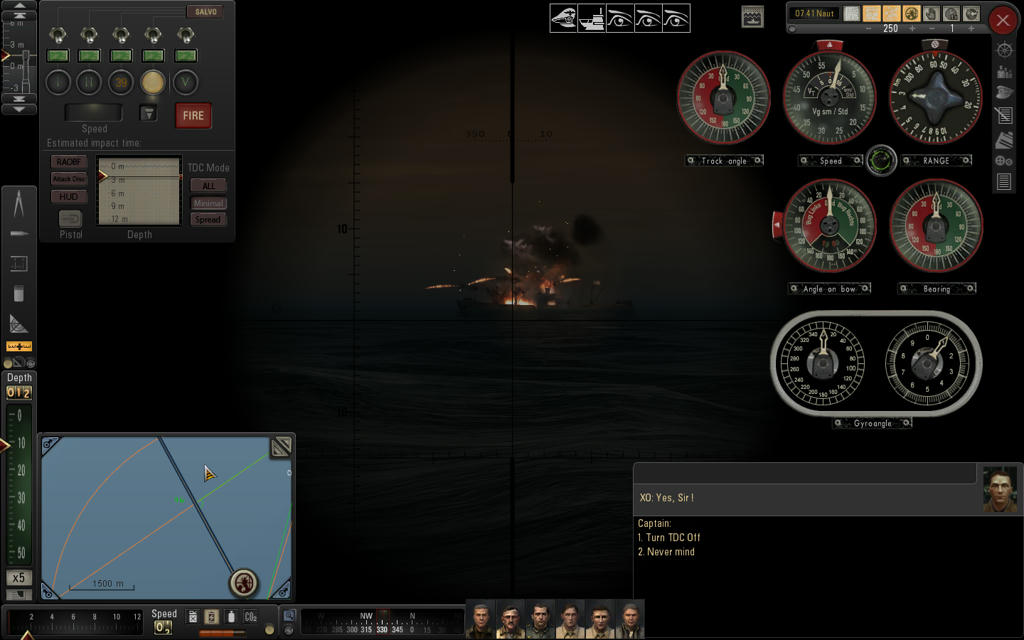
__________________
|
|
|
|
 |
| Tags |
| torpedo, trigonometry, zero gyro |
|
|


 Linear Mode

