SUBSIM Radio Room Forums


SUBSIM: The Web's #1 resource for all submarine & naval simulations since 1997

Go Back   SUBSIM Radio Room Forums > Silent Hunter 3 - 4 - 5 > SH4 Mods Workshop
Forget password? Reset here

Reply
 
Thread Tools Display Modes
Old 04-22-08, 07:44 AM   #61
M. Sarsfield
Ace of the Deep
 
Join Date: Aug 2007
Location: Tulsa, OK
Posts: 1,016
Downloads: 0
Uploads: 0
Default

Nice research, Nisgeis. You're definitely on the right track and we're all benefitting from it.

A little off topic, here's a nice post-war manual on how to set up a firing solution, different roles of the firing solution party, etc. I think this is a must-read for every WWII sub simmer. Definitely a must-read for n00bs.

http://www.hnsa.org/doc/attack/index.htm
__________________
MJS
USS Batfish Volunteer/Reenactor
www.ss310.com
www.ussbatfish.com


Communism killed over 100M people and all that I got was this lousy signature.*

*http://www.hawaii.edu/powerkills/COM.ART.HTM
M. Sarsfield is offline   Reply With Quote
Old 04-22-08, 09:38 AM   #62
AVGWarhawk
Lucky Jack
 
AVGWarhawk's Avatar
 
Join Date: Jun 2005
Location: In a 1954 Buick.
Posts: 28,277
Downloads: 90
Uploads: 0


Default

Quote:
Originally Posted by Nisgeis
Quote:
Originally Posted by elanaiba
Looks great

BTW, just wanted to add something from a pdf on the MkIV TDC that I have around here:
Thanks for the info! From what I can find out, nothing explicitly states anything is directly entered for calculation, apart from the own speed and own course inputs. The reference that said 'fed into' etcetera may have been worded ambiguously. From what I can make out, all input were manual (except for own course and speed) and everything else had repeaters. I'm a bit hazy on method of correction to these values - I've seen reference to handles used to adjust range being different to the input to set range, but that's for future research. I wanted to get a copy of 'Torpedo Data Computer' but it doesn't seem to in print.

They seem to have increased the number of receivers, so not only did the TDC have a calculated range and the radar range feed and associated bearing details, the radar station also had a calculated range and obviously it's own range unit and bearing. This seems to have been to reduce the amount of verbal communication required to improve efficiency and it also allowed the TDC operator and Radar operator to check for bearing rate error. I did find one reference to the deck gun having repeaters for radar range and bearing for fire control.

Anyway, here's a picture posted on the forum before by akdavis in this thread http://www.subsim.com/radioroom/show...ht=Radar+range

The last picture posted is dated, so is of the correct era, but it is from the seaplane tender USS Cumberland Sound, so I don't think it would be an SJ set (note no bearing lines).


The poster said that this is an image taken just after entering of Tokyo Bay. The circular disturbance in the very centre of the scope is the saturation caused by strong radar returns from the sea. These returns occur between 2,000 yards on a calm sea up to 6,000 yards during heavy seas. As this was taken in Tokyo Bay, I'm going to say the sea returns are from 2,000, which would mean this picture was taken on the 20,000 yard setting.

All these questions are good, because it makes me check and I find out something else that was in the stuff I've read, but didn't go in and stick in my brain.
Great pic and from what I recall seeing. As you can see there is a lot of "clutter" on the screen from other things other than ships. Ship are elongated and have a bit of curve as shown above and what you have created thus far is darn good. If we can at least find a way to create "clutter" on the screen from weather, sea state or a seagull sitting on the mast, that would be great. Returns from a distance show as one big mass which the game does already. As you draw closer the mass becomes individual masses or ships. Currently the radar is just too good. So, how to make some fuzzy mess on the screen and force me have to really study the radar to find my targets bearing and speed? These are the questions:hmm: Next thing to study............how to make the darn thing break down? Many times the radar was broken or died during patrols. I'm not asking much Nice work


To think Nisgeis(I spelled it right:rotfl this all started with a texture on a submarine you worked on. :hmm: Hmmmm....another awesome modder in the making.
__________________
“You're painfully alive in a drugged and dying culture.”
― Richard Yates, Revolutionary Road
AVGWarhawk is offline   Reply With Quote
Old 04-22-08, 10:03 AM   #63
M. Sarsfield
Ace of the Deep
 
Join Date: Aug 2007
Location: Tulsa, OK
Posts: 1,016
Downloads: 0
Uploads: 0
Default

I don't see a sweep line in that photo, either.
__________________
MJS
USS Batfish Volunteer/Reenactor
www.ss310.com
www.ussbatfish.com


Communism killed over 100M people and all that I got was this lousy signature.*

*http://www.hawaii.edu/powerkills/COM.ART.HTM
M. Sarsfield is offline   Reply With Quote
Old 04-22-08, 10:49 AM   #64
akdavis
Samurai Navy
 
Join Date: Mar 2005
Location: Fort Worth, Texas
Posts: 597
Downloads: 0
Uploads: 0
Default

Quote:
Originally Posted by M. Sarsfield
I don't see a sweep line in that photo, either.
Possibly because of low shutter speed. And thank you Nigeis for digging up that old thread.
__________________
-AKD
akdavis is offline   Reply With Quote
Old 04-22-08, 05:46 PM   #65
LukeFF
Silent Hunter
 
Join Date: Apr 2005
Location: Riverside, California
Posts: 3,610
Downloads: 41
Uploads: 5
Default

Quote:
Originally Posted by M. Sarsfield
I don't see a sweep line in that photo, either.
Draw an imaginary line from bearing 190 up towards the center, and you'll see it.
__________________


ROW Sound Effects Contributor
RFB Team Leader
LukeFF is offline   Reply With Quote
Old 04-23-08, 12:33 AM   #66
LukeFF
Silent Hunter
 
Join Date: Apr 2005
Location: Riverside, California
Posts: 3,610
Downloads: 41
Uploads: 5
Quote:
Originally Posted by LukeFF
Reducing verbal reports to an absolute minumum was one of the benefits of the Mark 4 TDC. I'll pull out the section where Norman Friedman talks about it in his book and post it here, later on today when I'm not so tired.
Alright, here we go:

Quote:
Generated bearing and range could be transmitted automatically to the JT and SJ, with corrections fed back to the TDC. The key quantities were the rates at which range and bearing were changing. Now they could be measured almost directly. For example, the JT operator could estimate the rate at which a target's bearing was changing. He could set JT to turn at that rate; if it stayed on the target, the estimate was correct. The measured bearing rate could be fed back to the TDC. Mk 4 could handle more torpedo range and speed settings than its predecessor. Maximum tracking range was up to 30,000 yd, and target speed was to 40 kt. Maximum torpedo gyro angle was 150 degrees. The postwar Mk 106 submarine fire-control system was based on Mk 4.
__________________


ROW Sound Effects Contributor
RFB Team Leader
LukeFF is offline   Reply With Quote
Old 04-27-08, 02:58 PM   #67
Nisgeis
Ocean Warrior
 
Join Date: Jan 2008
Posts: 2,909
Downloads: 77
Uploads: 11
Default

Ignore the range rings, they are temporary to help with calibration. I'm having trouble with this, for various technical reasons, one being the pixel shader is single pass and I can't store any information at all.

After some early success hooking the radar range readouts up to the engine RPM gauges (which was a bit strange), Here's the state of play at the moment:


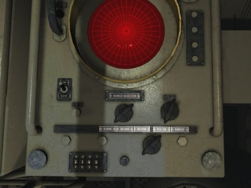
The game engine only sends the info in meters, but then again the radar range is in meters, even if you choose imperial. The range is correct up to 9,999 meters, after which the first digit refuses to move. I haven't been able to find a send range to TDC button - does anyone know if there is one for the U-Boat campaign on the German set?
Nisgeis is offline   Reply With Quote
Old 04-27-08, 06:41 PM   #68
Q3ark
Watch Officer
 
Join Date: Apr 2007
Location: York, England
Posts: 346
Downloads: 47
Uploads: 0
Default

Quote:
Originally Posted by Nisgeis
I haven't been able to find a send range to TDC button - does anyone know if there is one for the U-Boat campaign on the German set?
Have had a look on the German set, there dosen't appear to be a send range button. The only switches are on/off, sweep/focus and a range selector just like th ones on the U.S. set.

Have to say your new radar screen is looking good
__________________
Johnny was a chemist's son,
But Johnny is no more.
What Johnny thought was H20
was H2SO4.
Q3ark is offline   Reply With Quote
Old 04-28-08, 08:27 AM   #69
Nisgeis
Ocean Warrior
 
Join Date: Jan 2008
Posts: 2,909
Downloads: 77
Uploads: 11
Default

Quote:
Originally Posted by Q3ark
Have had a look on the German set, there dosen't appear to be a send range button. The only switches are on/off, sweep/focus and a range selector just like th ones on the U.S. set.
Can you set range manually in the U-Boats, or only with the stadimeter and sonar?
Nisgeis is offline   Reply With Quote
Old 04-28-08, 09:16 AM   #70
Q3ark
Watch Officer
 
Join Date: Apr 2007
Location: York, England
Posts: 346
Downloads: 47
Uploads: 0
Default

Quote:
Originally Posted by Nisgeis
Can you set range manually in the U-Boats, or only with the stadimeter and sonar?
Let me have a look see :hmm:

You can set range manually using the interface on the attack map from 300 to 10000 meters just like SH3.

You can also alter the bearing to target, angle on the bow and speed. Wish we could do that from the attack map in the fleet boats
__________________
Johnny was a chemist's son,
But Johnny is no more.
What Johnny thought was H20
was H2SO4.
Q3ark is offline   Reply With Quote
Old 04-29-08, 02:32 PM   #71
M. Sarsfield
Ace of the Deep
 
Join Date: Aug 2007
Location: Tulsa, OK
Posts: 1,016
Downloads: 0
Uploads: 0
Default

Nisgeis,

Are you closer to solving the dial issue not turning over after 9,999? Do you plan on adding a 5th digit, since the radar is supposed to go out to 80,000 yards?

I guess the range read-out is hardcoded, since that wasn't a factor/option that the devs counted on needing both measurement systems for. I have a conversion spreadsheet for yards and meters, anyway. So, that's not a big deal.
__________________
MJS
USS Batfish Volunteer/Reenactor
www.ss310.com
www.ussbatfish.com


Communism killed over 100M people and all that I got was this lousy signature.*

*http://www.hawaii.edu/powerkills/COM.ART.HTM
M. Sarsfield is offline   Reply With Quote
Old 04-30-08, 10:18 AM   #72
Mav87th
Stowaway
 
Posts: n/a
Downloads:
Uploads:
Default

Here is some warshots in color of the radar in function. Both of the scopes are present in it at 9:16.


Sorry i forgot the link - doh

Last edited by Mav87th; 04-30-08 at 01:31 PM.
  Reply With Quote
Old 04-30-08, 01:16 PM   #73
M. Sarsfield
Ace of the Deep
 
Join Date: Aug 2007
Location: Tulsa, OK
Posts: 1,016
Downloads: 0
Uploads: 0
Default

Pics?
__________________
MJS
USS Batfish Volunteer/Reenactor
www.ss310.com
www.ussbatfish.com


Communism killed over 100M people and all that I got was this lousy signature.*

*http://www.hawaii.edu/powerkills/COM.ART.HTM
M. Sarsfield is offline   Reply With Quote
Old 04-30-08, 05:16 PM   #74
akdavis
Samurai Navy
 
Join Date: Mar 2005
Location: Fort Worth, Texas
Posts: 597
Downloads: 0
Uploads: 0
Default

Quote:
Originally Posted by Mav87th
Here is some warshots in color of the radar in function. Both of the scopes are present in it at 9:16.


Sorry i forgot the link - doh
Hmm...I have my doubts about the PPI clips shown. It is not from the same, black-and-white film as the A-Scope imagery, which seems in keeping with the quality of low-light film at the time. Furthermore, it is an extremely "clean" image, which suggests Hollywood interpretation to me. I suspect it might be from a movie.

Most of this has probably been posted before. There are these from the USS Cobia:


Quote:

Description:A 10 cm surface-search and torpedo- control for installation on submarine.
Number of operators:One.
Power supply:SJ-1; 1.4 kva, 115 v, 60 cps. SJ SJ-1Maximum reliable range (miles): Bombers, 500 ft. 5. 5. Battleships 8. 12. Cruiser 8. 12. Destroyers 6. 8. Submarines (sur- faced) 3. 6. Beacons S Band Horizon. same.Resolution: Range (yd.) 50. 50. Bearing (deg.) 5. 5.Accuracy: Range (yd.). 25+-.l%. 15+-.1% (precision sweep). Bearing (deg.) +-0.3. 0.3 degree (with lobe switch).Minimum range (yd.) 250. 250.Indication and data output:
Range: 5-inch A-scope with range step and dial. Main Sweep: 60,000 yd. Expanded Sweep 20,000 yds. Precision sweep on 40,000 yds. 1,500 yds. either side of mark.
Bearing: Relative bearing read from train indicator. Pip match is optional.
PPI: A 5-inch PPI is provided with SJ-a and SJ-1
Ranges: 8,000, 20,000, 80,000 yd. 160,000 yd. delayed sweep.
Other: Provisions for IFF indication are present.
Transmitter specifications: Frequency (Mc) 3000. R-f source Magnetron,706AY. R-f lines Wave guide. Pulser type Thyraton-SJ; Peterson Co: 1 SJ2. R-f peak power (kw) SJ-20; SJ-1-50. R-f average power (kw) 0.018-SJ. Pulse rate (pps.) SJ-600 & 1800; SJ-1- 1500+-150. Pulse length (micro second) 0.25.Receiver specifications: Type Superheterodyne. Stages. 6 i-f; 3 video. Local oscillator 707A; SJ-1-726B. Intermediate frequency (Mc) 60. Band pass (Mc). 5 i-f; 5 video. Mixer Crystal SJ-1; grounded. grid triode-SJ. Noise, db above theoretical. 10.Antenna specifications: Total weight (lbs.) SJ-300; SJ-1-330. Feed Wave guide. Reflector: Old type Solid unhoused reflector. New type Slotted. Shape Truncated paraboloid. Size SJ-10" high x 30" wide.H.P. beam width: Horizontal 9 degrees. Vertical 29 degrees.Polarization Horizontal.Gain (db) 19 (SJ-1).Scan Continuous rotation through 360 degrees at 1 to 8 r.p.m. by motor or it may be trained manually. Left-right lobe switching. Divergence is 5 degrees. Elevation fixed.Tube complement.-1 type 705A, 1 type 706A or 706AY, 1 type 707A, 1 type 708A, 1 type 709A, 1 type 713A, 1 type 722A, 1 type 2X2/879, 1 type 5HP1, 4 type 5U4G, 1 type 6AB7, 14 type 6AC7, 1 type 6H6, 10 type 6L6, 10 type 6SN7GT, 4 type 6SQ7, 2 type VR-105/30, 3 type VR-150-30, 1 type 813, 2 type 836, 4 type 991.
Dimensions and weights (SJ-1) Unit Navy Type Length Width Depth Weight Pampanito No. Inches Inches Inches Pounds Serial #Antenna assembly CW-66AFC 31 1/2 30 15 350Transmitter re- CW-43AAF-1 20 5/8 18 7/8 13 190 #12,C.T. ceiver.Range indicator CW-55AAL-1 16 3/4 11 3/8 20 3/4 110Plan position in- CW-55ADE 14 3/8 13 1/8 19 7/8 120 #6,C.T. dicator.Range unit CW-23ACC 6 9/16 9 1/2 18 3/4 67 #67,C.T.High voltage rec- CFZ-2OAAR-1 10 5/16 12 18 7/16 100 #6,P.R. tifier.Regulated recti- CFC-2OAAQ 18 1/4 10 21/32 17 5/8 115 #6A,6B P.R. fier (2).Main control unit. CFC-23ADH 14 1/4 15 1/4 13 125 C.T.Bearing indicator CW-55ADD 8 12 8 20 C.T.,C.R.Motor generator CW 12 37 3/4 12 110 control unit.Adapter control CW-23ABX 5 3/4 5 3/4 4 5/8 6 1/2 C.T.,P.R. unit.Junction box (2) CW-62AAB 14 17 9/16 4 5/8 32Motor generator CG-21AAS 15 1/8 13 7/16 44 3/8 450 set.Range transmitter 6 1/2 9 1/32 9 1/2 26Test Equipment.-ABM wave meter and OBU echo box included. OBU,C.T.Literature.-SJ instruction book (Eng. 188). SJ-1 instruction book (Ships 258).
Quote:
SV

Description.-An 8 cm. aircraft warning radar for use on submarines to supersede the SD.
SV-1 has instantaneous automatic volume control, fast time constant. Also uses SS indicating unit.
Number of operators.-One
Weight installed.-3,400 lb.
Power suppIy. 6 kva, 115 volts, 60 cps, 1 phase. Maximum reliable range. (miles): Bombers, at 30,000 ft 7.5 Bombers, at 10,000 ft 10 Fighters, at 10,000 ft 12 Battleships 12.5 Cruisers 15 Destroyers 10 Submarines, surfaced 7.5Resolution: Range (yd.) 5.7 Bearing (deg.) 5Accuracy: SV SV-1 Range (yd.) +-(50+0.1%). 15+-1%. Bearing (deg.) +-2. 1/2.Minimum range (yd.) 400. 400.Indication and data output:
Range: SV uses SJ-1 indicator (5 inch A scope with 10, 30 mi. ranges). SV-1 uses SS range indicator (3 inch A scope 10, 30 mi. ranges).
Bearing: SV-1 uses SS bearing indicator (3 inch B scope with 4,000 yd. range).
P.P.I.: 5-inch scope. Provision for four radar repeaters.
Ranges: 4, 10, 40 miles on SV; 4, 10, 20, 80 miles on SV-1
Other: Provisions for IFF trigger and display.
Antenna specifications: Total weight (lb.) 500 including pedestal but not torque tube. Feed Wave guide. Reflector: Type Slotted csc2 parabola. Size 2 ft. high x 4 ft. wide. H.P. beam width: Horizontal 5.5 degrees. Vertical 60 degrees. Polarization Horizontal. Gain (db) 30. Scan 360 degrees at 0 to 6 r.p.m. by motor. D-c motor control.Transmitter specifications: Frequency (Mc.) 3400-3700. R-f Source Magnetron. R-f Lines Wave guide. Pulser type Nonlinear coil. R-f peak power (kw) 500. R-f average power SV-0.2; SV-1-0.15.(kw). Pulse rates (pps) SV-300 +-5%; Pulse length (micro sec) 1.


SV Radar PPI.


SV Range Indicator
Receiver specifications: Type Superheterodyne. Stages 7 i.f. 2 video. Local oscillator 2K29. Intermediate freq. 60.(Mc.). Band pass (Mc.) 2 i.f.; 3 video. Mixer Crystal IN21B. Noise, db above 13. theoretical.Tube complement.-2 type 1B27; 1 type 2AP1; 1 type 2K29; 2 type 3B24; 4 type 5D21; 2 type 371B; 10 type 6AG7; 6 type 6AK5; 7 type 6AL5; 1 type 6S5GT; 18 type 6SN7GT; 1 type 6V6GT; 3 type 705A; 1 type 807; 1 type 4J36; 1 type 2X2; 5 type 5HP1; 17 type 6AC7; 4 type 991; 7 type OD3/VR150; I type 6Y6-G; 1 type 3B24; 1 type SFP7; 1 type 6H6GT; 2 type 6L6-GA; 2 type 991; 6 type SR4GY; 2 type 393A; 2 type C6J.

Literature.-Instruction book, Ships 340. Dimensions and weights Unit Navy Type Length Width Depth Weight Pampanito Inches Inches Inches Pounds Serial #Antenna projector 66AJV 27 48 36 400Transmitter-receiver 43ACW 22 21 70 800 C.R.Echo box 13ABG 16 8 7 10Torque tube drive 10AFB 16 22 30 500 unit.Motor drive gear unit 10AFD 11 18 13 125Motor drive shaft (#1) (#1) (#1) 14Spline shaft drive unit. 1OAFC 11 17 9 50Spline shaft (#2) (#2) (#2) 100Spline shaft upper 10AFE 8 6 8 25 bearing unit.Synchro unit 21ADE 12 17 11 90Main control unit 23AGD 18 21 18 100 #28,C.R.Range unit 23ACC 19 10 7 60 #28,C.R.PPI 55ADE 20 12 15 120 #28,C.R.,#6,C.T.Range indicator 55AGE 21 17 13 110 #28,C.R.Regulated rectifier 2OADN 27 20 18 250 #28,C.R.Auxiliary rectifier 20ADO 27 20 18 200 #28,C.R.Wave guide switching 24AAK 20 13 9 75 C.R. unit.Dummy antenna 66AJW 20 11 C.R.Motor controller unit. 23AGE 12 12 14 50 #28,C.R.Motor control rectifier. 2OADP 27 20 18 300 #28,C.R.Antenna drive motor. 21ADC 21 11 11 260Adaptor control unit 23ABX 5 6 10 7 C.T., C.R.Frequency power meter TS-295/UP 10 9 9(#1) 1.5 diameter. Length cut on job.
(#2) 2.25 diameter. 14' in length.
REFERENCES:

The information enclosed here is excerpted from:
Catalogue of Naval Electronic Equipment-April 1946- NavShips 900,116.
__________________
-AKD

Last edited by akdavis; 05-01-08 at 04:13 PM.
akdavis is offline   Reply With Quote
Old 05-01-08, 03:49 AM   #75
Nisgeis
Ocean Warrior
 
Join Date: Jan 2008
Posts: 2,909
Downloads: 77
Uploads: 11
Default

Quote:
Originally Posted by M. Sarsfield
Nisgeis,

Are you closer to solving the dial issue not turning over after 9,999? Do you plan on adding a 5th digit, since the radar is supposed to go out to 80,000 yards?

I guess the range read-out is hardcoded, since that wasn't a factor/option that the devs counted on needing both measurement systems for. I have a conversion spreadsheet for yards and meters, anyway. So, that's not a big deal.
Sorry for the late response, I've been testing away and got some worrying results.

The variables that you can attach to dials are hardcoded and I don't think there's a way to add in a fifth dial, but that's what people said about arced contacts right? 10km is about 11,000 yards, so should be enough range to start a track with. There may be a method to add it in another way, but it might be a prohibitively heavy load for the graphics card.
Nisgeis is offline   Reply With Quote
Reply

Tags
arced radar contacts


Posting Rules
You may not post new threads
You may not post replies
You may not post attachments
You may not edit your posts

BB code is On
Smilies are On
[IMG] code is On
HTML code is Off

Forum Jump


All times are GMT -5. The time now is 07:40 AM.


Powered by vBulletin® Version 3.8.11
Copyright ©2000 - 2025, Jelsoft Enterprises Ltd.
Copyright © 1995- 2025 Subsim®
"Subsim" is a registered trademark, all rights reserved.