Silent Hunter 
Join Date: Sep 2010
Posts: 3,975
Downloads: 153
Uploads: 11
|
Algebraic Firing Solution
An alternate method for torpedo firing solution:
I made the computations for this method some time ago when I was playing SHCE. I've used it quite a
lot in that game, but also in SH 3 and SH 4. It will work with any SH game and does not rely on any game
exploit. I became interested in this after reading the S class boats did not have any TDC, and had to make
use of other methods for obtaining a torpedo firing solution. I know others have made use of similar
solutions, so I thought I'd post my version.
For those who have only used the in-game TDC, this type of method is fundamentally different. It
involves calculating a firing solution for the target as it reaches a discrete point, whereas the TDC
allows continuous updates of the firing solution. This means with the USN TDC, one can launch at any point;
the sub can change course and wait until a more favorable track is obtained, increase speed, etc., etc.
None of this "breaks" the solution. Not so with this method. It is like the difference between methods of
lead in duck hunting; continuous tracking allows the shot to be made any time after proper lead is
established, whereas "trapping" (aiming at a point ahead) requires the shot to be made at the moment the
target reaches the calculated point.
So, if this method is more limited, why use it? This is a fair question. The main reason is
realism. The S class did not have any TDC and had to use some sort of calculation method, such as the Mk
VIII angle solver. Unfortunately, we don't have this in the game. [It should be noted here that the
difficulties involved in using the Mk VIII angle solver, lead to the development of the TDC, and was a big
step forward in fire control.] The other reason I use this method is just because it is both challenging
and interesting (at least to me), to do it this way. It gives one a deeper appreciation for the Torpedo Data
Computer.
This method requires the gyro mechanism be set to fire straight ahead (or behind), and a
longitudinal spread be used, if any. The method is simply four equations for calculating the following:
1. Lead Angle
2. Time to Position
3. Track Range
4. Torpedo Run Time
Some would consider only the lead angle to be necessary, but I feel that the track range and
torpedo run time should be known in any proper method. The time to position is not necessary, but is
helpful in practice. Knowing this allows one to lower the periscope, instead of leaving it up waiting for
the target to reach the firing bearing. The track range not only provides a run time for the torpedos, but
also gives one an idea of the quality of the set-up, and allows a change in plan to obtain a better range,
if that is indicated. Of course, the torpedo run time provides an indication of whether the torpedos hit
the target, or just exploded somewhere out there. (It also tells you how good your plot and data were.)
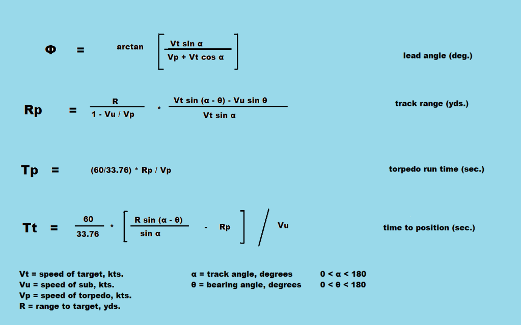
Below are the equations used:

To utilize the method, you must have all the usual elements of firing data, the range, the bearing
angle, the track angle, the target speed, and torpedo speed. Many will notice I didn't mention the angle on
the bow. This is because it is implicit in the track angle. If you know the track angle, you can get the
AoB. If you know the AoB, you can get the track angle. They are really two halves of the same coin. I
originally derived the equations in terms of the AoB, on the theory that I might want to make an attack
without plotting, in an emergency, but in practice, I did not use them this way. I played around with them,
trying to put them into a more intuitive or simpler form. Finally I altered them to use the track angle,
since USN documents use this more often. One form is not really better than the other, but I think using
the track angle is a little less confusing than using the AoB.
It doesn't matter how you obtain the data, as long as you have it. Naturally, the more accurate it
is, the better your firing solution will be. Garbage In Garbage Out, as they say.
Here is an example to illustrate:
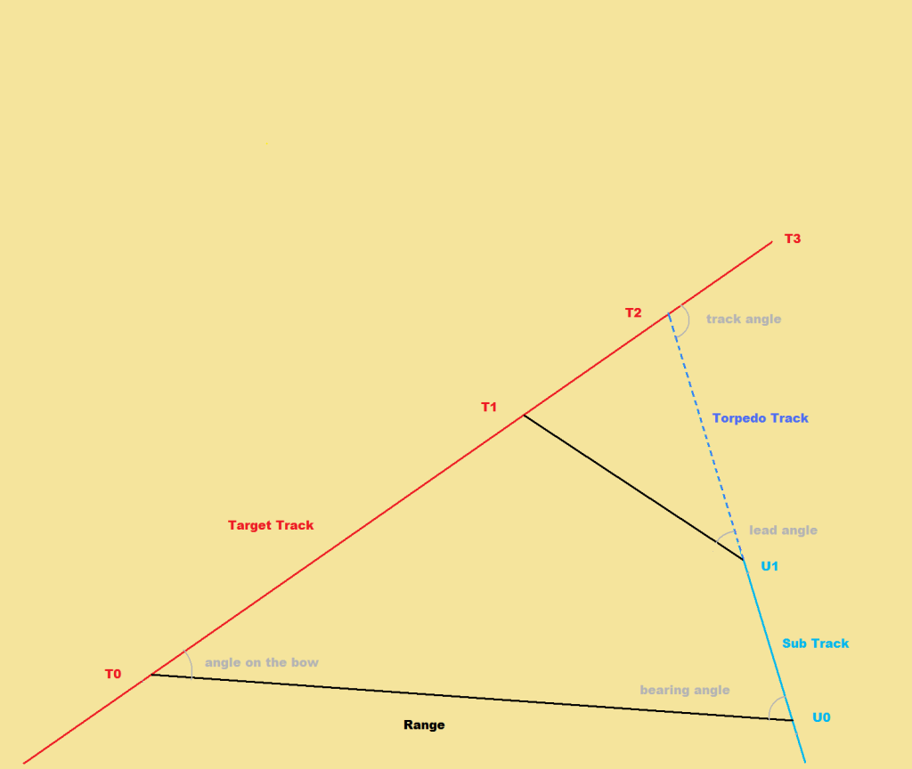
[Note that the diagrams are not to scale, and are just to help illustrate the concept.]

In this example, the final observation is made with the sub at U0 and the target at T0. The
calculations are made with the Range (T0 to U0), the Track Angle (Angle T3_T2_U0) and the Bearing Angle
(Angle T2_U0_T0). The torpedo(s) are launched when the sub is at U1 and the target at T1. They impact with
the target at T2.
Let's say you have been tracking a target and have good estimates of it's speed and course. You
have turned on to your attack approach course and do not intend to change speed. It is important to
understand that the calculated firing solution is rendered invalid if you change course or speed before you
launch your torpedos. The same goes, if the target should happen to change course or speed. You get from
your final observation:Torpedo Track Angle__________________________ 135 deg.
Bearing Angle*________________________________ 94 deg.
Range to Target____________________________ 2,600 yds.
Target Speed___________________________________ 9.5 kts.
Sub Speed______________________________________ 2.0 kts.
Torpedo Speed_________________________________ 30.0 kts.
*I deliberately used the term Bearing Angle instead of relative target bearing. Relative Target
Bearing, 266 deg., Angle T2_U0_T0 (measured clockwise) cannot be used, instead the Bearing Angle, Angle
T2_U0_T0, (measured counter-clockwise) must be used, (i.e. 360 - 266 = 94). If in the above example, the
target was to starboard (right), the Relative Bearing 94 deg. could be used without alteration. But, when
the target is to port (left)
, the Relative Bearing of 266 deg. will not give correct answers. This is
because of the sine function. In this case the bearing angle is 360 - Relative Bearing, and the Firing
Bearing will be 360 - 16.1 deg. instead of 16.1 deg.
Doing the calculations yields:
Lead Angle____________________________________ 16.1 deg.
Time to Position_____________________________ 582 sec.
Track Range________________________________ 1,757 yds.
Torpedo Run Time_____________________________ 104 sec.
Using this solution for an attack, one would turn the scope to 343.9 or 344 deg. bearing and launch
on the target when it reaches that point. Spread the torpedos by launching on different sections of the
ship as they pass by. The time to position tells you it will take 582 sec. to reach that bearing. In
theory, you could submerge and fire at that time, without any visual observation, but I have never tried to
do it this way. Using the scope with a visual reference reduces the effects of errors which are likely to
be present in the data. If the time to position is significant, as in this case, one can make use of the
time by refining the estimates of speed and course, or plotting out alternate attack approaches, rechecking
calculations, etc. If the target reaches the firing bearing too early, or late, it is an indication that
either the calculations or firing data are in error.
Back to our example. Let's say you don't like the set-up and want to get closer. Using all the
above data, except the sub speed, which we increase to 11 kts., and doing the same calculations we get:Lead Angle____________________________________ 16.1 deg.
Time to Position_____________________________ 858 sec.
Track Range________________________________-2,897 yds.
Torpedo Run Time_____________________________-172 sec.
What! Negative range? Negative time? I know what your thinking. What kind of torpedo voodoo is
this!? Before you turn off your computer in disgust, let me explain. It turns out that if the sub in
question goes on this track at 11 kts., it will cross the target's track in front of the target. In other
words, there is no bow shot in this set up. (If you were plotting this out in the game, you would probably
notice this before you did the calculations. If your just pulling numbers out of your hat, you probably
would not. Don't ask me how much time I wasted because of this.) However, this brings up another question.
What if we want to make a stern shot? Can the equations be used to do this? The answer is yes, but we must
make a few changes in our procedure.
First, we must cross the target's track before we can get the proper data. The geometry changes
when we cross the track, so the initial data will not give us the correct answers. We can make our final
observation the moment we cross the track, if we want to, or any time after. As a side note, I should point
out that the collision course speed in our example is 6.25 kts. Below this speed, the target will cross in
front of the sub, above this speed our sub will cross in front of the target. We should choose a speed
significantly above or below this value.
Collision Course Speed = Vt * [sin (alpha - theta)/ sin theta]
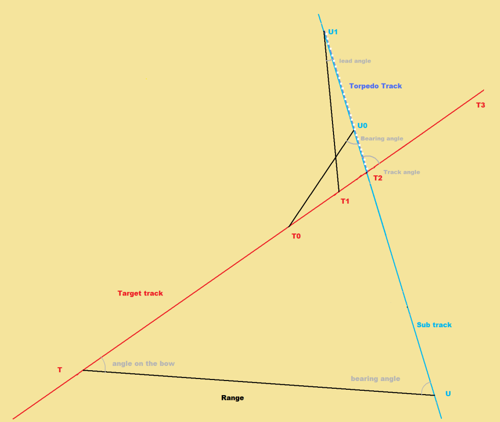
This is what the set will look like for a stern shot:

This is the same original course and target data, but with the tracks extended.
So, if we do the math, we find with our first example that at 11 kts we will cross the track after
390 seconds. As I said we can make our final observation now or anytime after. At 490 sec. after our
initial position we find:Torpedo Track Angle____________________________ 45.0 deg.
Bearing Angle*_________________________________ 28.6 deg.
Range to Target_____________________________ 1,549.6 yds.
Sub Speed______________________________________ 11.0 kts.
*Relative target bearing is 208.6 deg., we must use 28.6, (208.6 - 180 = 28.6).
All other data is the same as before.
Here are the changes we must make in our procedure:
We must consider the geometry from the stern of the boat. (Pretend the stern is the bow here.)
1. torpedo track angle changes as we cross the track. The geometry is such that the track angle for
the stern shot is 45 deg.(angle T3-T2-U0). This is the supplementary angle to the original track angle,
(i.e. 180 - 135 = 45).
2. The bearing angle as taken from the stern. (Angle T2_U0_T0).
3. We must use the negative value of sub speed, - 11.0 kts. (We are moving away from the target's
track now.)
4. The lead angle obtained is also from the stern. (Angle T2_U1_T1, firing bearing = 180 +/- lead
angle.)
Here is the data for our calculations:Torpedo Track Angle___________________________ 45.0 deg.
Bearing Angle*________________________________ 28.6 deg.
Range to Target____________________________ 1,549.6 yds.
Target Speed___________________________________ 9.5 kts.
Sub Speed_____________________________________-11.0 kts.
Torpedo Speed_________________________________ 30.0 kts.
Crunching the numbers, we obtain:
Lead Angle____________________________________ 10.4 deg.
Time to Position_____________________________ 117 sec.
Track Range________________________________ 1,342 yds.
Torpedo Run Time______________________________ 79 sec.
So, with this we rotate our scope or TBT to 190.4 deg (180 + 10.4) and wait for the target to cut
across our sight.
I tried to use precise figures in the examples so anyone who wishes to can make a scale drawing or
otherwise check the math. If there are any doubters (I suspect there will be a few), the easiest way to
check is to consider the length of the relevant triangles and use the Law of Sines to calculate the
numbers.
Some might consider a method which requires calculations or this sort to be cheating. But since we
have no Mk VIII angle solver, we are left with the choice of either using the game TDC (obviously not
ideal), or some method of our own. This method brings limitations which are, at least, somewhat comparable,
to what one would have using a Mk VIII angle solver.
Last edited by TorpX; 03-02-13 at 04:21 PM.
Reason: restored links to images
|


 12-23-12, 05:32 PM


