
|
|
SUBSIM: The Web's #1 resource for all submarine & naval simulations since 1997
|
SUBSIM: The Web's #1 resource for all submarine & naval simulations since 1997 |
 04-23-07, 10:20 AM
|
#166 | |||||
|
Engineer
 Join Date: Apr 2007
Location: Conning Tower - repairing the radar.
Posts: 200
Downloads: 8
Uploads: 0
|
Quote:
Quote:
I wondered what the actual surface area of A6M2 Zero was and I looked on the web and discovered this (to my amazement) ; http://rwebs.net/avhistory/history/Zeke32.htm EDIT NOTE (thanks Redwine!) .... divide my sqft by 10.75 below .... argh 1. Wing Surface Area = 232 sqft (70.71 m2) (21.58 m2) 2. Horizonal Tail Surface Area = 51.68 sqft (15.75 m2) (4.80 m2) 3. Fuselage Surface Area = 116 sqft ( 35.35 m2) (10.79 m2)... I couldn't find the surface area for the fuselage so I calculated it using the drawings and rounded down .. about half the wing area. Total = 399.68 sqft (121.82 m2) (37.17 m2)... exposure of zeke directly above observer. If you add in the frontal area of 58 sqft (17.67) (5.39 m2) ... again, my calculation based on drawing ... your total is 139.49 m2 (42.56 m2) Using this calculation based on my TEST #1 below : Zeke @ 500m altitude 1. Bottom Surface exposed = 2.88 m2 2. Front Surface exposed = 17.66 m2 Total = 20.54 m2 (1.91 m2) Zeke @ 1000m altitude 1. Bottom Surface exposed = 5.76 m2 2. Front Surface exposed = 17.65 m2 Total = 23.41 m2 (2.17 m2) EDIT NOTE (thanks Redwine!) .... divide my sqft by 10.75 above .... argh Note how in the Aircraft CFG file for the A6M2 they have a Length and Width value (which is the same for G4M) of L=11.5 W=13.8 ... total 158.7 ... really close to what I calculated (139.49). I tried changing this to like 100x100 but appears it didn't change the detection result using a surface of 100. I might try this test again. I believe that it's actually using a polygon count or something instead of a basic box dimension "height x length" or "width x length" like from a flat source like the ship's dimensions or aircraft L x W. What you see is what ya got .... But .... I've been playing with the Surface area value and I discovered it's not as simple as thinking a value of 100 means that it's won't detect anything below 100 m2. I think it's a "constant" that changes with range. If you increase range using a constant surface of 100 you also "push" the 100 trigger further out. Basically, you're pumping out more power (gain) and expecting a larger return of energy. Unfortunately, SH4 default values might not equal the result we want, ie set maxrange to real world range expecting real world detection. I did some tests back in v1.1 with the SD with these results (the size of the A6M2 worked beautifully as a "base 100") ; TEST #1 MaxRange = 55560 Surface = 100 Resultant Detection Range : 1. H8K / H6K @ 33,700 m +/- 500 2. G4M @ 26,500 m +/- 2000 3. Zero @ 21,100 m +/- 500 TEST # 2 MaxRange = 55560 Surface = 200 Resultant Detection Range : 1. H8k /H6K same as test #1 2. G4M same as test #1 3. Zero @ 14,600 +/- 300 TEST # 3 MaxRange = 111120 Surface = 100 Resultant Detection Range : 1. H8k /H6K same as test #1 2. G4M same as test #1 3. Zero @ 31,900 +/- 500 TEST # 4 MaxRange = 40000 Surface = 100 Resultant Detection Range : 1. H8k /H6K same as test #1 2. G4M same as test #1 3. Zero @ 14,600 +/- 300 As you can see, TEST #2 = TEST #4 , although max range was reduced about 15k. The larger aircraft aren't affect at all with a value of 100. I used a crazy value of 4500 in one test and only detected the H8K and H6K at about 9000 m. Using the SD that Jace11 created along with Ducimus' modifications I believe we should increase the surface area to eliminate ship contacts since we've already have the coverage area pointing away from the horizon it's only exposing (my theory) the ship's superstructure and masts. However, increasing the surface will also decrease the range at which you detect the aircraft. It needs to be juggled (like Ducimus did in v1.1  ) but if you juggle too many values at one sitting you'll end up chasing your tail. ) but if you juggle too many values at one sitting you'll end up chasing your tail.Before I embarked on my SD testing in v1.1 I asked myself these questions : 1. Is the SH4 sensor world flat? .... yes, I think so, even though visually it appears ships "grow" as they get closer (curvature of earth). 2. Are the sensor's dynamic? ... meaning, searching in a moving 3D world. Yes, Jace11 proved that with his "stormy sea" posting.  3. Are the sensors seeing through the water? ... thus including the part of the ship below the ocean when it calculates surface area .... I'm still debating this one! 4. And the BIG question ... What is the detection routine order for radar? ... Again, still debating this but Ducimus posted that at PreciseRange it's automatic. If an object meets the Surface requirement then it's detected, otherwise within PreciseRange. Anyway, sorry to run off into a lecture ...  . Please take no offense . Please take no offense Someone please correct me if I'm wrong!!! Or tell me to put the calculator away!!! Picture example of my thought process .... :hmm: 
Last edited by Mraah; 04-23-07 at 11:07 AM. |
|||||

|

|
|
04-23-07, 10:35 AM
|
#167 |
|
Seasoned Skipper
 Join Date: Mar 2005
Location: UK
Posts: 683
Downloads: 104
Uploads: 1
|
You see, I can get the SD to pick up ONLY air contacts but only when the sea is flat and in a sterile single mission (done by raising the angle off the horizon).
I have a set up now that will still pick up surface contacts via SD, but not all the time... I was also thinking... How did weather affect radar performance... I ask because you could reduce radar effectiveness via the sensors.cfg in the CFG folder to take into account bad wave conditions, therefore we could have SJ and SD working well in nice clear weather, but it a storm, make them nearly useless - or untrustworthy... That could be realistic if the radar sets were inhibited by such things, otherwise, its just another workaround... I may try later |
|
|
|
|
04-23-07, 10:41 AM
|
#168 |
|
Sea Lord
 Join Date: Jan 2002
Location: San Martin de los Andes, Neuquen, , Argentina.
Posts: 1,962
Downloads: 10
Uploads: 0
|
I will read your topic in detail Mraah.... but i note some thing...
into square meters enters 3.28 by 3.28 feet .... it is 10.75 square feet by each sqaure meter. So in example... 2. Horizonal Tail Surface Area = 51.68 sqft (15.75 m2) The correct value must be.... 2. Horizonal Tail Surface Area = 51.68 sqft (4.8 m2) please check it.... prior to spend more job and time. I will read your post now in detail....
|
|
|
|
|
04-23-07, 10:52 AM
|
#169 | |
|
Grey Wolf
 Join Date: Nov 2005
Location: Mar del Plata, Argentina
Posts: 871
Downloads: 0
Uploads: 0
|
Quote:
Ref
__________________

|
|
|
|
|
|
04-23-07, 11:08 AM
|
#170 | |
|
Engineer
Join Date: Apr 2007
Location: Conning Tower - repairing the radar.
Posts: 200
Downloads: 8
Uploads: 0
|
Quote:
Thanks Redwine ... too much coffee!!! Much apologies for thinking so stupid! Refresh the thread, I made the edit changes in yellow. |
|
|
|
|
|
04-23-07, 11:32 AM
|
#171 | ||
|
Engineer
Join Date: Apr 2007
Location: Conning Tower - repairing the radar.
Posts: 200
Downloads: 8
Uploads: 0
|
Quote:
Sorry to doubt your 100m2 post.... I made the correction. What was I thinking (I blame the calculator... yeah, that's the ticket) Here's something I pulled out of this book below. Shows how much you guys did a great job on the radar ... even with the holes, etc... TECHNICAL AND MILITARY IMPERATIVES A Radar History of World War II pg. 473 VERTICAL LOBES PATTERNS 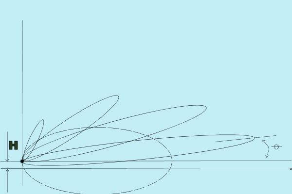 "Vertical Lobes patterns. If an antenna has it's beam pointed parallel to a conducting surface, such as ocean or very flat ground, and is located at a height H above it, the lower half of the pattern is reflected and interferes with the direct radiation, producing a pattern of vertical lobes. In the diagram the dashed curve represents the pattern in free space; the solid curves the first four lobes of the resulting radiation. The reader can easily image the confusion for an untrained observer when an aerial target approaching from the right disappears momentarily as it leaves the first lobe and proceeds to the second. The angle of the first lobe relative to the antenna axis (in radians) is approximately equal to the wavelength divided by four times the antenna height above the surface." I don't know the SD wavelength but the SV is 8cm. You can calculate (I'm afraid to use my calculator now since I made a fool of myself  ) an angle, but remember, the lobe is FAT in the middle and POINTY on the end so probably add/subract about 5-10 degrees to the FAT part to get the lobe width at half the distance. ) an angle, but remember, the lobe is FAT in the middle and POINTY on the end so probably add/subract about 5-10 degrees to the FAT part to get the lobe width at half the distance.
|
||
|
|
|
|
04-23-07, 11:59 AM
|
#172 | ||
|
Engineer
Join Date: Apr 2007
Location: Conning Tower - repairing the radar.
Posts: 200
Downloads: 8
Uploads: 0
|
Quote:
WWII radar ... I don't know. It was in it's infancy, so with that, they probably got saturated with return signals bouncing every which way. Ground clutter is another thing, hence you might read a minimum range on posted documents. I'll see if I can find a chapter on rain in the book. |
||
|
|
|
|
04-23-07, 12:00 PM
|
#173 |
|
Sea Lord
Join Date: Jan 2002
Location: San Martin de los Andes, Neuquen, , Argentina.
Posts: 1,962
Downloads: 10
Uploads: 0
|
One thing more...
What is SS into the tweak file... SV was airborne, but SS ? Was for planes or ships ? |
|
|
|
|
04-23-07, 12:08 PM
|
#174 | ||
|
Sea Lord
Join Date: Jan 2002
Location: San Martin de los Andes, Neuquen, , Argentina.
Posts: 1,962
Downloads: 10
Uploads: 0
|
Quote:
Quote:
Still on job .... |
||
|
|
|
|
04-23-07, 12:15 PM
|
#175 | |
|
Engineer
Join Date: Apr 2007
Location: Conning Tower - repairing the radar.
Posts: 200
Downloads: 8
Uploads: 0
|
Quote:
The SV in the tweakfile is my guess. The SS was in the orginal v1.1 tweakfile that Ref linked. It was sensor #8. DropDownName=NSS_SS I don't know what the SS could be. I can't find any WWII references to it. Update : found the info SS = An X Band (3cm) surface search radar installed on a few boats at war's end. ST = A microwave surface search radar with it's antenna in the periscope. It used the SJ installation to give range, but the bearing information was a function of the periscope's pointing. Last edited by Mraah; 04-23-07 at 02:43 PM. |
|
|
|
|
|
04-23-07, 12:21 PM
|
#176 | |
|
Engineer
Join Date: Apr 2007
Location: Conning Tower - repairing the radar.
Posts: 200
Downloads: 8
Uploads: 0
|
Quote:
We'll have to nickname you Columbus II for rediscovering the world is round !!!
|
|
|
|
|
|
04-23-07, 12:46 PM
|
#177 | ||
|
Engineer
Join Date: Apr 2007
Location: Conning Tower - repairing the radar.
Posts: 200
Downloads: 8
Uploads: 0
|
[quote=Mraah]
Quote:
To simulate this in SH4 I can only think that perhaps we need to allow CREW EFFICENCY to be TRUE (good operator can find and track a target better than a green horn) and adjust the weather effect so it basically see's almost nothing in bad weather ????? Would be nice if they displayed pockets of cluttered "unknown" radar targets in groups from small to large. That would be awesome. In summary, my opinion ; rain = mask waves = range degradation Both together = useless peice of .....
|
||
|
|
|
|
04-23-07, 12:57 PM
|
#178 | ||
|
Grey Wolf
Join Date: Nov 2005
Location: Mar del Plata, Argentina
Posts: 871
Downloads: 0
Uploads: 0
|
Quote:
To simplify things sensors in shx series don't use physics for it's calculations, that's why you can pick a ship on the sonar if it's behind a land mass. Ref
__________________
|
||
|
|
|
|
04-23-07, 01:01 PM
|
#179 |
|
Seasoned Skipper
Join Date: Mar 2005
Location: UK
Posts: 683
Downloads: 104
Uploads: 1
|
yeah that would be why the radars dip below the horizon - so you can see contacts beyond visual range. There are other things I've seen that suggest this.
|
|
|
|
|
04-23-07, 01:18 PM
|
#180 | |
|
Engineer
Join Date: Apr 2007
Location: Conning Tower - repairing the radar.
Posts: 200
Downloads: 8
Uploads: 0
|
Quote:
Have you observed this with radar as well and can I expect the same with the sonar? ie can hear it but not displayed. Possibly a feature for the sonar... reflected sound, probably not. I think too much, when I should use the KISS principle, keep it simple stupid .
|
|
|
|
|
 |
|
|


 Linear Mode

