
|
|
SUBSIM: The Web's #1 resource for all submarine & naval simulations since 1997
|
SUBSIM: The Web's #1 resource for all submarine & naval simulations since 1997 |
|
|
 08-25-13, 01:03 AM
|
#1 |
|
Sailor man
 Join Date: Mar 2011
Posts: 47
Downloads: 27
Uploads: 0
|
Intercepting Targets
Learning to Intercept targets is crucial for success in Silent Hunter III. Table of contents [hide] 1 Introduction 2 Plotting the target's course and speed 3 Finding the intercept point 4 Example intercept 5 Running a Box Pattern Intercept 6 Example box pattern intercept 7 Claren's Easy Course-to-Target Plotting Method 8 See also 9 Other resources 9.1 Silent Hunter III specific 9.2 Historical Introduction The goal of a good intercept is to get you into firing range (500-700 meters) with the ship passing right in front of you. Ideally, your boat should be at exactly 90° to the path of the target facing it as it passes by. This allows you to fire fire your torpedos at 0° Gyro angle. Gyro angles within 10° of 0 work well. Beyond that, your torpedo may fail, or hit at a bad angle. Ensuring that your range is within the 500-700m range, directly abeam of the target, will make your limited supplies of torpedos much more effective. Plotting the target's course and speed In order to reach an ideal intercept position, you need to know the target's speed and heading. Both can be determined by submerging at low speed or stopped and taking several hydrophone readings. Note that you must have the No map contact update realism setting disabled for this to work. You should take several hydrophone readings over time. Zoom in on the end of the black or grey sonar contact line and put an X with the marker there. Ensure that you are zoomed in far enough to see the grid lines, or you won't get a very accurate position fix. Even so, you will be off. The farther the contact, the larger the error. The error will always be one of range, the bearing is accurate. You should note the exact time of each mark that you make, to be able to later determine the target speed. If possible, try to make each mark at an interval of 3 minutes and 15 seconds. This allows you to use the 3 minute rule to easily calculate the target's speed. In any case, you must know the elapsed time between your marks if you want to know the speed of the target. With hydrophone readings, the updates come about every minute. If you ask the sonarman to follow the nearest contact, they come every 15 seconds or so. So keep in mind the 3 minute rule will be a rough estimate of speed. If you are moving and the target is moving, you can just turn time compression to 64 and eyeball it. You can say pretty fast if the target is moving much faster than you. Getting an exact speed with timing is much faster in game time and will allow you to intecept fast moving targets more often. Fast, for merchants anyway. Once you have at least 3 marks on the map that are about kilometer or more apart, use the ruler to draw a line from the first one through the last one. This is the ships estimated course. The ships real course will be +/- 5° and +/- 500 meters at 15 Kilometers. Keep in mind this course is an estimate and plan to update it accordingly. You can now calculate your targets speed (distance = rate x time), or using the 3 minute rule. Finding the intercept point A line from your ship that meets the target's course line at 90° is the closest intercept course you have to the target's course. If the target is more or less coming at you, just plot a course that takes you right into its path, minus about 500 meters. Using the target's calculated speed you can determine approximately when the target will arrive near your intercept point. Ensure that your U-boat has enough speed to reach that point well before the target! It is important not to take a diagonal path compared to the targets course. This will not leave you in a good firing position and you will waste many torpedoes. Once you get the hang of it, you may want to take a diagonal path to get you further ahead of the target, then make your turn to 90° at the end. Example intercept 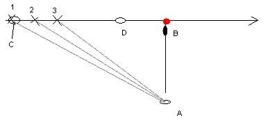 Sub starts (A) and takes several readings on target (C). Gray lines represent sonar readings. Sub moves to intercept location (B) and arrives early. Target arrives at (D) as sub is settling into position and getting final readings on exact course. Running a Box Pattern Intercept If you can't make it into the ships path in time or the target is moving away from you, you need to run a box pattern to get where you need to be. Mark out a course that is exactly parallel to your target's course. Make sure that this course is at least 2KM from the targets course at night or in bad weather. Go at least 5 KM out in clear weather during the day to stay beyond visual range. Surface your boat and make flank speed along this course until you have enough lead to get into position and be submerged when the target arrives. You should stop once in a while and submerge to confirm that the target is still on course. It might take you a full day or more running at top speed on the surface to outflank the target. That's what flank speed is for. It might also be impossible to overake the target, even at top speed. In that case, dive and set ahead slow the opposite direction along the targets course and hope it's a well travel sea lane. Example box pattern intercept 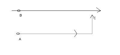 Sub (A) can't directly intercept target (b) so it runs a box intecept to arrive at (C) before the target. Don't forget to submerge to get sonar readings an confirm the target is still on course. --SaintD 11:28, 12 May 2005 (EEST) Claren's Easy Course-to-Target Plotting Method Note from Dantenoc: --This method produced faulty results, and has been replaced with the correct procedure... I had previously left it alone and had only posted a link to the revised method, but a lot of people kept reading the incorrect version. Sorry Claren... you allmost had it but you switched around two of the triangles' legs And now for the new and improved revised version. For the short explanation, only read what's on top of the images (after the "Step X:" title and before the picture). For a more complete explanation read the rest also. Step 1: The setup One of the biggest reasons for the early success of the u-boat was coordinated intel received from BdU. The germans had broken the british radio codes and regularly intercepted messages that allowed them to know the whereabouts of the enemy boats and convoys. Other sources of such privileged information included sightings by other U-boats and Luftwaffe airplanes, who reported their findings back to headquarters. Silent Hunter III simulates this by ocationaly marking ship icons in your nav-map even though they're way out of your range. If you can succesfully tap into that information, you'll soon become Germany's top U-boat ace without much effort Your U-boat, located at point 1, receives a contact report of a ship located at point 2. Take notice of the contact's speed and heading, which you can obtain by clicking on him on the nav-map. 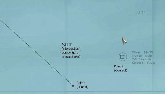 Slow means around 6 knots, medium means about 9 knots, and fast... well, I never bother with those (why? because they're probably warships and Doenitz wants you to concentrate on merchant shiping). Obviously, in cases like these, when the contact is so far away, there's absolutely no point in racing toward the contacts reported location... he won't be there any more by the time you get there. No, rather, our hope is to intercept the ship at some point 3 were we'll both meet. In other words, go to the spot where he is going to be by the time you get there. Now the big question is: where exactly IS that spot?!?! Step two: To figure out where the "Intercept point" is, start by clicking on your ship with the protractor tool (marked as P1 on the image), then click on the contact (marked as P2 in the image), and then drag the second leg of the protractor tool off into the direction where the contact is heading. Your nav-map should look like this: 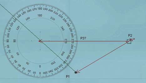 Step three: Using the ruler start measuring from the contact's position of into the direction where it's heading. Measure a distance representative of it's speed. In this example the contact was reported as slow, so I measure 6 kms to represent 6 knots. Your nav-map should look like this: 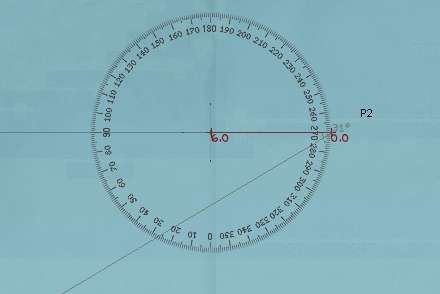 Note that the distance of 6kms used is merely a mnemonic representation of the contact's speed of 6 knots, It has nothing to do with the actual 11.118 kilometers that the ship will travel in one hour at that speed, or anything like that. You could have just as easily used any other scale to represent speed... like for example: 10 kms for every 1 knot, or 0.1 kms for every 1 knot or even weird scales like 2.5 kilometers for every 1 knot. The trick here is to pick a scale that you are most comfortable with and to STICK WITH IT. As long as you are consistent in your scale choice you should have no problems whatsoever. |

|

|
|
08-25-13, 01:07 AM
|
#2 |
|
Sailor man
Join Date: Mar 2011
Posts: 47
Downloads: 27
Uploads: 0
|
Step four:
Using the compas, draw a circle centered at the end of the measurement you just did (labeled P3b in the image). The radius of this circle should be your intercept speed. In this example, I think I have a good angle of aproach, and don't feel like wasting too much fuel, so I leave the circle's radius at 12kms, representing the 12 knots to wich I'll speed up to to intercept the target. Take special notice of where the circle intercepts the leg of the protractor that goes from your ship to the contact (labeled P1b in the image). Your nav-map should look like this: 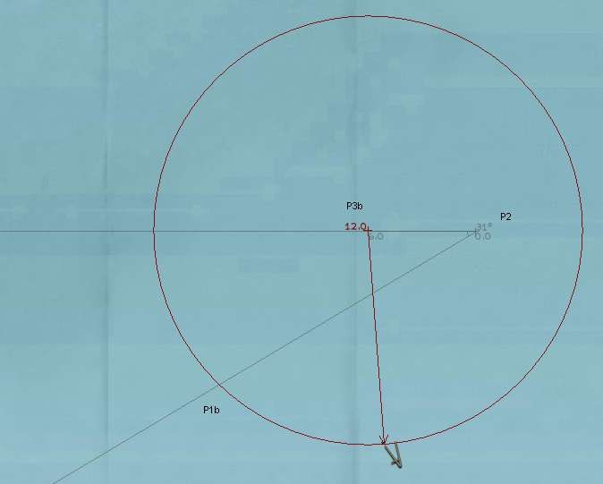 Two points of interest here. First; you can choose whatever intercept speed that you desire (within reason). If the contact is coming somewhat towards you, and isn't too far away to begin with, you can intercept very easily with an economical 9knots speed for your U-boat. If the contact is heading away from you, or is too far, or is moving very quickly, you will most likely want to use a quicker speed, but never, ever use flank speed... it's just a waste of fuel when used in long range maneuvers like this. The second point of interest is the use of the circle to measure your U-boat's speed instead of a ruler. The reason for this is simple: you're supoused to measure this distance along the course that you will take to intercept the contact... but how can you do that if we haven't figured out yet what that course will be?... luckily the circle's radius measures distances IN EVERY DIRECTION (all around) and that's why we use it. Also, rember to be consistent in your scale choice, by using the same scale as the one you used to measure the contact's speed. If your drawn circle is so small that it does'nt make a P1b point in your diagram (i.e.: it does'nt touch the line between your U-boat and the contact) then that means that the intercept speed you have chosen is too slow, and you'll never be able to catch the contact. Chose a faster speed thus making a bigger circle. Also, on very rare ocations, when the contact's speed is superior to your's (but an intercept is still possible), the circle might touch the U-boat/contact line in TWO places. In that case, the point of interes (P1b) is the the closest one to your U-boat. Step 5: With another protractor tool, click at the center of the circle (P3b), then the point where the circle intercects the line that goes from your U-boat to the contact (P1b), and from there click in the direction of the contact. TAKE NOTICE OF THIS IMPORTANT ANGLE... Lets call it Angle A. Your nav-map should look like this: 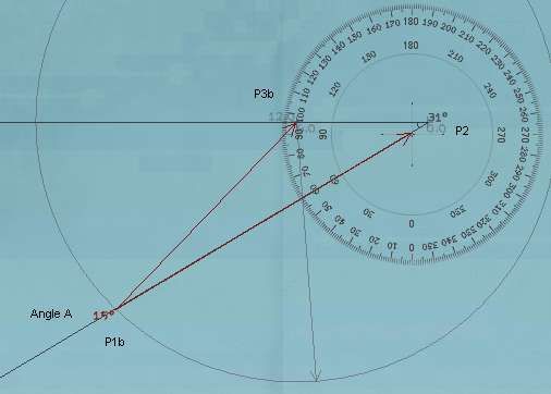 The easiest way to do the last leg of this protractor would have been to actually click on the contact for the third (last) click. However, this is not really needed... al we care about is the angle that is being formed and that will remain the same if you click exactly on the contact or in any other point that is in the same exact direction. Step 6: Using yet another protractor tool, click on the vicinity of the contact (if you can't click exactly on the contact because of all the overlaping protactors, then simply click somwhere along the line formed by your U-boat and the contact), then on your u-boat, and then drag the second leg of the protractor so that it PERFECTLY REPLICATES ANGLE A. That's it, your done: Point Three, indicated by the thick black arrow in the image below is where the target is going to be just at the moment of interception... SO START HEADING FOR IT, HER KALEUN!!! 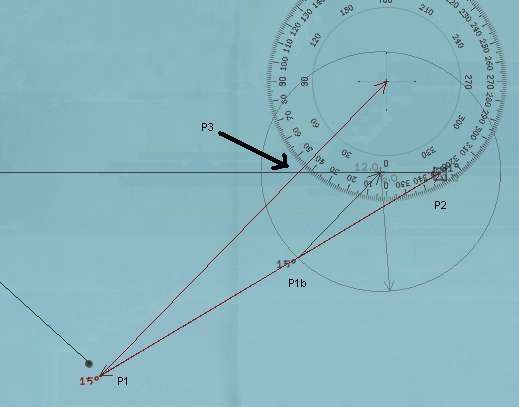 Here's the magic of trigonometry at work. The little triangle you made in figure 5 (points P1b, P2 and P3b) solves the problem of interpecting the target IF your U-boat where positioned perfectly for a one hour interception course (it would have to start at P1b). Our situation isn't as ideal of course, but pitagoras says that what holds true for little triangle holds true for big ones, as long as all their inner angles are the same. So, if your intercept took two hours instead of the one hour represented by the small triangle, your solution triangle would be bigger by a factor of two, and your U-boat would have to start at a point twice as far away from the contact as point P1b, but you'd still have the SAME INNER ANGLES in your solution triangle as in the little one. In our case it will take X amount of hours (unknown as of yet) to intercept, so our solution triangle would be bigger by a factor of X (which we don't know) and our U-boat would have to start from our present location (which is great for us) and our solution triangle would still have the all the same inner angles (which we DO know) as the little one... that's why we replicate angle A with our last protractor. Keep in mind that the result may not allways be so perfect that you end up ramming the enemy ship. Theoreticaly it should, but there are several limiting factors to this method: 1)Being a grafical solution, it depends greatly on your ability to draw correctly and exactly, with very high precision. Each mistake done with the drawings whill lead you to a less than perfect result (use high zoom-ins on the nav-map to mimize this potential for error) 2)The data provided to you was vage and imprecise in nature (the targets speed and heading) 3)Enemy ships don't travel in a straight line forever, so you have to intercept them before they make any significant course changes, otherwise you'll miss them. |
|
|
|
|
08-25-13, 01:12 AM
|
#3 |
|
Sailor man
Join Date: Mar 2011
Posts: 47
Downloads: 27
Uploads: 0
|
Automatic Targeting
With the Manual Targeting option disabled in Realism Settings the targeting process is very simple. All the player must do is point the periscope at the target and launch a torpedo. It is not necessary to find the range, AOB or speed of the target manually, as the entire process of plotting a solution is handled automatically by the game. Be sure to open the torpedo tube before you fire ('Q' key, or right click the weapons officer to enter his station, and flip the relevant switch). If you don't, it will take a few seconds to open and possibly spoil your shot. If you don't have the target locked, and you forgot to open the door, try to keep the crosshairs on target until the torpedo is launched. Even with Automatic Targeting you can still alter torpedo speed, depth and detonator type (impact or magnetic) Also, if you have a mixed load of torpedoes which have different speeds you need to click on the speed setting dial in the F6 TDC screen when switching tubes to update the firing solution. e.g. you fire a T1 then switch to a TII in another tube, you`ll need to click on the speed setting dial (even though the TII only has one speed) to get an accurate solution. See also: Salvo Periscope display Hit probability indicator In automatic targeting mode, the periscope or UZO will show a small coloured triangle when a contact is visible and centred in the optics. The triange can have three colours; green, orange or red, which correspond approximately to the chance of making a successful shot. The colour changes depending on the required Gyro angle of the torpedo when it leaves the U-Boat. Green - Gyro angle of +/-5°; that is from 355° to 004°. Orange - Gyro angle of +/15°; that is from 315° to 044° Red - Gyro angle of more than 15° in either direction. In general, the smaller the gyro angle, the more chance of a successful hit, but this can still be affected by target range, torpedo settings etc. Manual Targeting Table of contents [hide] 1 General Targeting Considerations 2 Notepad Method 2.1 Identify the target 2.2 Find the range 2.3 Estimate the AOB 2.4 Determine the speed 2.5 Taking the shot 3 Full Manual TDC 4 Credits General Targeting Considerations In short, the Torpedo Data Computer (TDC) is used to calculate a gyro angle for your torpedos. The gyro angle, in turn, determines the course a torpedo will take after leaving your u-boat en route to hitting a moving target. The TDC requires four pieces of information to calculate the correct gyro angle: Angle on bow (AoB) - This is the direction of travel of the target relative to your u-boat's direction. See Angle on bow for more information. Bearing - This is the angle at which you observe the target. Speed - This is the speed of the target. More precisely, it is the relative speed between you and the target. Range - Although it does not effect the gyro angle as much as the three above, range DOES have an effect on the angle and thus checking the range prior to shooting is always a good idea. There are two methods for entering the required data into the TDC, the Notepad Method, and Full Manual. Notepad Method The notepad method is the "standard" SH3 method of performing a manual attack. The notepad is visible in the top right-hand corner when you are at the attack (F3) or observation (O) periscope, or UZO (F6, if surfaced) stations. The following steps are much easier if you lock the target in your periscope or UZO using the 'L' shortcut key. To use the notepad, you must perform the following four steps in the correct order: Identify the target Find the range Estimate the AOB Determine the speed It is possible to use the notepad to enter just some of the targeting data. However each step is dependent on the earlier ones in the list, so you cannot, for example, determine the speed without having first estimated the AOB. You can, however, use the notepad to calculate the range and AOB, but then enter the speed directly into the TDC without using the notepad's target-speed tool. See the TDC page for more information. Identifying the target Enlarge Identifying the target Identify the target Once you have your target visible through your scope or UZO, press N to bring up the recognition manuals. Find the correct vessel, and tick the square box in the lower right-hand corner. Until you do this, none of the other functions will be possible. It is worth noting the Draft of the vessel while you have the recognition manual open. This will be useful if using magnetic triggers on your torpedoes. Find the range To find the range, you can use the stadimeter control. Click the word Range on the notepad to open the correct page. Using your mouse within the periscope view, put the central cross hair on the waterline of the target, and then click once on the stadimeter control icon in the corner of the notepad page. This changes your cursor to a line which can move and down within the periscope view. The idea is to move this line up to the top of the highest mast of the vessel, and then click again. By taking the angle between the centre-line and the line you've just set, along with the known height of the mast from the recognition manual, the game can automatically calculate the range. See the Stadimeter page for more detailed instructions on finding the range. Stadimeter The stadimeter is the range-finder built in to your Attack Periscope and UZO. In Silent Hunter III it is also available from your Observation Periscope. Using the stadimeter To operate the stadimeter, you must be using the notepad method of manual targeting. See that page for information on how to use the notepad. Once you have identified your target using the Recognition Manual, you can click on the word Range on the notepad to begin your range estimation using the stadimeter. Range finding The principle of the stadimeter is that you should align the horizontal line running through the centre of your periscope with the waterline of your target vessel, and the higher, moveable, line with the top of the highest mast of the target. By knowing the angle formed between these lines, and the height of the mast from the recognition manuals, the system can calculate the range to your target. If you are unsure of which is the highest mast, you can theoretically find this information on the relevant page of the Recognition Manual. This is still not always obvious however. In the image below, notice that the mast height is automatically filled in when you select the correct ship with the recognition manual. If you have not selected the correct ship then your range will not be accurate. Immediately before using the stadimeter, you should try to ensure that the central (lower) line is as close as possible to the waterline of the target. Then, after clicking on the Stadimeter icon (circled on the screenshot), you will be able to use the mouse to control the moveable upper line in your periscope view. It is also possible, although awkward, to move the periscope head (and therefore the lower line) using the up and down arrows (or Ctrl-Up and Ctrl-Down for finer movement) while the stadimeter is in use. When you are happy that the placement of the lines accurately reflects the height of the masthead, click once and your range will be filled in on the notepad page. You can repeat this process as often as you like until you are happy with the result. Once you are satisfied with your range, don't forget to then click the tick-box to send the range to the main notepad page! In the example image below the lines are perfectly positioned ready to submit the range. In heavy seas it is quite a challenge to come up with an accurate result using the stadimeter. Practice makes perfect! 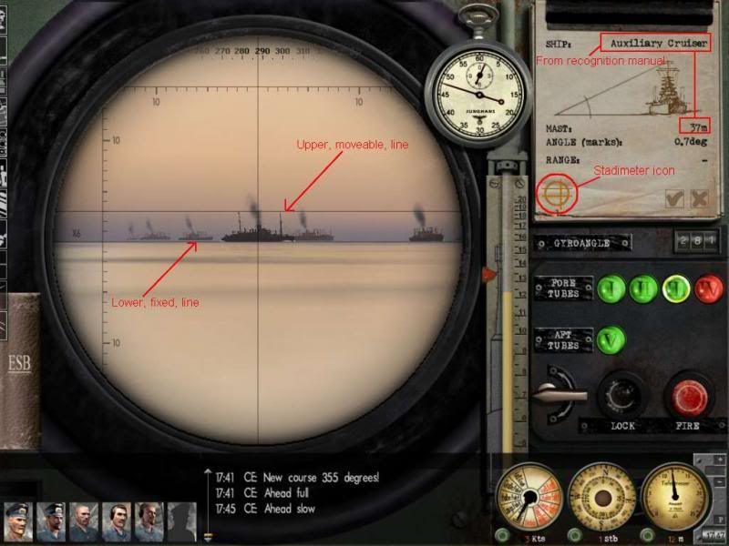 Once you have an estimated range, click the tickbox to send that range back to the main notepad page. Estimate the AOB Click on the words Angle on bow on the notepad to bring up the AOB page. Here you can estimate your angle on bow from the target, and mark it by dragging the icon around the ship on the diagram. Note that the central vessel in the diagram is your target, and you are estimating where your U-Boat is, in relation to that target. To assist in determining the AOB, you can use the AOB page on the recognition manual. You can also calculate it before-hand using knowledge of the target course and bearing from your U-Boat. Once satisfied with your estimated AOB, click the tickbox to send that range back to the main notepad page. Determine the speed The final step in the process is to determine the speed of the target. The notepad includes a tool to assist you in doing that. Click the word Speed and a small timer icon will appear. By clicking this, you will start a timer and, as long as you have the target locked the system will begin tracking how far across your field of view the target moves. Use the Stopwatch to monitor the duration of your timing. After a suitable length of time - perhaps 15 seconds, you can click anywhere to stop the timer and the speed will be displayed. It is important that you are stopped or moving very slowly for this to be accurate. In addition, you will not get accurate results if the target is moving directly towards you, or away from you. Ideally for this to be accurate, you should be at All Stop, at a 90° AOB from the target. In general, the notepad device for determining target speed is only of limited use. It's worthwhile learning additional techniques such as the Three Minute Rule to accurately detect your target's speed. As before, you should click the tickbox to send the speed to the main notepad page. Taking the shot It is important that once back on the main notepad page, you click the tickbox a final time to send the complete set of the data to the TDC. If you update any of the data subsequently, you must ensure that you click the main tickbox again or that new information will not be used. Also, make sure you fire right after you place the final checkmark. If you do not, the AoB will change (this effect increases if the target moves fast). As the result, the torpedo will miss astern or hit the ship in the very rear. As well, make sure you open the tube door beforehand. Enjoy Full Manual TDC Paul "Wazoo" Wasserman has put together an excellent tutorial on doing manual targetting at: Wazoo's Manual Charting & Targeting Tutorial http://www.subsim.com/radioroom/showthread.php?t=206381 |
|
|
|
|
08-25-13, 01:17 AM
|
#4 |
|
Sailor man
Join Date: Mar 2011
Posts: 47
Downloads: 27
Uploads: 0
|
TDC
The TDC or Torpedo Data Computer is a calculating device installed in U-boats to assist in torpedo aiming. The TDC screen is selected by using the F6 shortcut key. Table of contents [hide] 1 Introduction 2 The TDC screen 2.1 Target data controls 2.1.1 Target bearing input 2.1.2 Target data 2.1.3 AOB input 2.1.4 Target speed input 2.1.5 Manual entry button 2.1.6 Gyro angle display 2.2 Torpedo controls 2.2.1 Tube selection 2.2.2 Tube/Salvo selection 2.2.3 Salvo spread angle 2.2.4 Torpedo running depth 2.2.5 Pistol selection 2.2.6 Torpedo speed selection 2.2.7 Tube selection and firing shortcut 3 Operating the TDC 3.1 Effect of realism settings 3.2 Manually entering targeting data 3.2.1 Target bearing 3.2.2 Target range 3.2.3 AOB 3.2.4 Target speed 4 See Also 5 Credits Introduction The basic function of the TDC is to to calculate the correct gyro angle for a torpedo to ensure that it will strike its target. The inputs needed to make this calculation are: The Angle on bow of the U-boat from the target The speed of the target The range of the target The bearing of the target from the U-boat The speed of the torpedo Given this information, the TDC can calculate the intersection point of the paths of the target vessel and the torpedo and set the gyro angle so that the torpedo will arrive at that point when fired. The TDC will automatically update the torpedo with the correct gyro angle as adjustments are made. The TDC has the following additional functions: Allow salvo shots, adjusting the gyro angles of individual torpedoes to achieve a specified "spread" angle. Allow adjustment of the running depth and pistol type of the torpedoes. Select the current torpedo tube(s) Fire the torpedo or torpedoes. The TDC screen 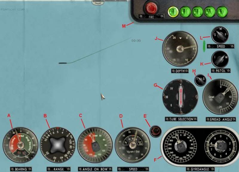 The TDC screen offers many gauges and controls. They can be split into two main groups Target data controls A - Target bearing input - This control allows the entry of the target's bearing from the U-boat. This should be the relative bearing; that is, the bearing from the bow of the U-boat irrespective of the course of the U-boat. This value can be set manually, or from the Notepad. B - Target range input - This control allows the entry of the target's range the U-boat. Each unit on the knob is 100m; therefore in the screenshot the selected range is 500m. This value can be set manually, or from the Notepad. C - Angle on bow input - AOB input This control allows the entry of the Angle on bow of the U-boat respective to the target. The red, left side of the dial is used for situations where the AOB is to port and vice-versa for to starboard. This value can be set manually, or from the Notepad. D - Target speed input - This control allows the entry of the target's speed in knots. This value can be set manually, or from the Notepad E - Manual entry toggle button - This button is used to toggle the manual entry mode of the TDC. If the button is red, then the values cannot be adjusted manually. Pressing the button (clicking with the mouse) will turn it green and allow the four input controls to the left to be manually adjusted. F - Gyro angle display. - This displays the calculated gyro angle. The left-hand dial shows the angle to the nearest ten degrees, and the right-hand dial shows a more accuate depiction down to 0.1°. In the screenshot, the left-hand dial is showing between 330° and 340°, and the right-hand dial shows approximately 7.7°. Therefore the complete gyro angle shown is 337.7°. The gyro angle cannot be manually adjusted by the user. Torpedo controls G - Tube selection - This knob allows selection of the torpedo tube(s) which will be used when the Fire order is given. Depending on the value of the Tube/Salvo selection knob, this will show either individual tubes, or pre-defined combinations of tubes for salvo shots. H - Tube (single shot)/Salvo selection - This control switches between an individual (tube) shot, and a salvo which consists of two or more torpedoes. As this value is changed, the Tube Selection control will change accordingly I - Salvo spread angle input - This control is only enabled if the Tube/Salvo knob is set to Salvo (S). The spread angle is the angle between the first and last torpedoes fired in a salvo. In the screenshot, the angle is set to 5°. This means that for a salvo of two torpedoes, the first will be 2.5° left of the aiming point, and the second will be 2.5° to the right. The angle between the two will therefore be 5°. J - Torpedo running depth input - This control allows you to select the running depth for your upcoming shot. K - Pistol selection - This knob allows you to choose the pistol type - either Impact or Magnetic - for your next shot. L - Torpedo speed selection - This control sets the speed of the torpedo. Note that not all torpedoes have adjustable speeds. In general, a faster speed makes for a higher chance of hitting the target, but at the cost of a reduced torpedo range. M - Torpedo selection and firing shortcut - The panel at the top of the TDC allows quick selection of a single tube. It will display which tube(s) are selected at all times. Each tube indicator can have three colours: Green - tube has a torpedo loaded. Red - tube is not currently loaded, but is either being reloaded now or is queued for reloading. Grey - There are no torpedoes available to reload the tube. Note that in SHIII versions 1.2 and 1.3 there is a bug in the torpedo selection. If you change torpedo selection to a torpedo with a different running speed, then the gyro angle will not be recalculated to take this new speed into account. In this case, you must click on the Torpedo Speed selection control to "remind" the program of the new speed. You will not see the speed change, although if you watch the Gyro angle display below it will be updated at that time. Operating the TDC Different parts of the TDC are used in different situations and realism settings. Effect of realism settings The Torpedo controls are useful irrespective of your difficulty level. It is always important to check or adjust your torpedo selection, speed and depth, as well as the salvo spread angle if a salvo shot is required. The use of the Target Data controls varies depending on your realism settings and method of targeting. For full automatic targeting, the Target Data control values (AOB, and target speed, bearing and range) will change automatically as you lock onto and track a target with either periscope or UZO. On the other hand, if you are using Weapons Officer assistance, then the values will be updated whenever you request a solution from the Weapons Officer. In both of these situations it is not necessary to manually check or adjust the Target Data control settings. For manual targeting, direct input of the values is essential: If using the notepad method of manual targeting, then some or all of the entries will be filled in for you when you submit the notepad data. If you have not filled in all of the values on the notepad, then you will still need to manually enter the others directly into the TDC. For full manual targeting without the notepad, all target data must be entered directly into the TDC. Manually entering targeting data Prior to entering data into the TDC, you must click the Manual entry button. This will make the button green and unlock the four TDC dials to the left of the button for manual input. The appearance of the dials will change slightly to indicate that you may now modify them directly. To adjust the controls manually, use your mouse to "grab" the dial pointer and drag it to the desired position. If using the notepad to determine some of the targeting data, submitting the notepad data will only modify those values which are actually entered on the notepad. As an example, if you have manually set the target speed and AOB, you can later use the notepad to determine the range. As long as you don't have notepad values for the range and AOB (ie they are marked with a dash (-) on the notepad), then when you submit the notepad data it will not affect your previously entered range and AOB figures. Target bearing If the manual entry button is red, therefore disabling manual entry, then the bearing dial will be updated automatically from your current optics (either of the periscopes or the UZO). If the button is green then you can manually adjust the dial. However, if at any time after a manual adjustment you click the manual entry button back to red, then your own values will be overridden by the current value from the optics! It is recommended, therefore, that the target bearing dial is not directly adjusted. If you need to modify the bearing, it is better to keep the manual entry button on red, and then rotate the periscope or UZO to the desired bearing. In general, the only time you need to modify the bearing is to enter a future AOB. In this case, you should point the optics to the desired bearing first as described. Target range This dial can be rotated to set the desired range. Each unit on the knob is 100m; therefore a range of 1500m should be set as 15 on the range control. When using the notepad, submitting the notepad data will override any manually set data only if the notepad contains a value for range. AOB A manually calculated AOB can be entered here. If the entered AOB is correct for the current value on the bearing dial, then it is not necessary to modify the AOB again unless the target changes course. The TDC will automatically adjust the AOB figure as the bearing from the U-boat to the target changes. When using the notepad, submitting the notepad data will override any manually set data only if the notepad contains a value for AOB. Target speed The speed of the target in knots can be manually entered here. When using the notepad, submitting the notepad data will override any manually set data only if the notepad contains a value for speed. |
|
|
|
|
08-25-13, 01:20 AM
|
#5 |
|
Sailor man
Join Date: Mar 2011
Posts: 47
Downloads: 27
Uploads: 0
|
Three Minute Rule
The Three Minute Rule (which, more accurately, should be called the Three Minute Fifteen Second Rule) is a simple way of determining your target speed Introduction By measuring the distance a vessel has moved over an interval of three minutes and fifteen seconds, it is possible to easily determine the speed. Of course, any measure of time and distance can be used to determine a target's speed, but the Three Minute Rule has the convenient advantage of equating a tenth of a kilometer to one knot of speed. For example: If over 3 minutes, 15 seconds the target moves 400m (0.4km), then the target speed is 4 knots. If over 3 minutes, 15 seconds the target moves 1500m (1.5km), then the target speed is 15 knots. In essence, take the distance travelled in that time in km, multiply by ten and that is the speed in knots. The math behind it: 1 knot = 1.852 kilometers per hour 3 minutes 15 seconds = 0.0542 hours .0542 hours * 1.852 kilometers per hour = 0.1004 kilometers =~ 1 knot Example This example assumes that the No map contact update realism setting is not enabled; that is, map updates should be turned on. The U-boat captain has spotted a small tanker at about 45 degrees off the U-boat's bow. Immediately he starts a plot to determine the target's course and speed. Zooming in on the navigation map (F5), a mark (Mark 2 in the example) is plotted exactly against the bow of the target. 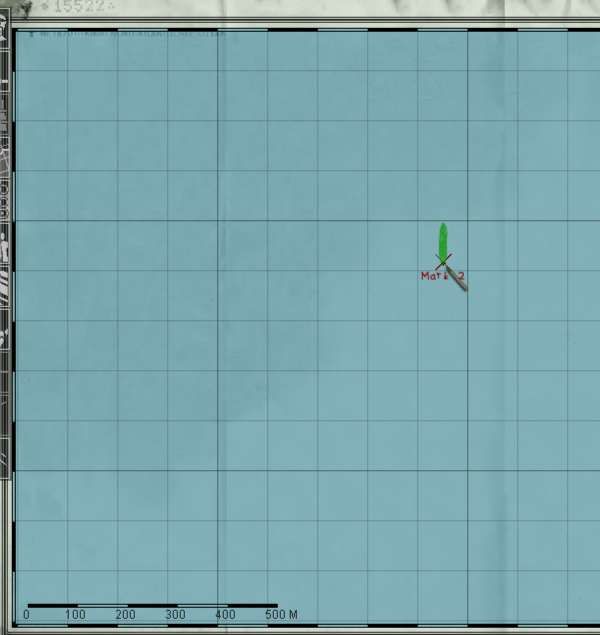 Making the initial mark for the plot Immediately after making the mark, the view is switched to the Attack Periscope (F3) and the Stopwatch is started (outlined in red) by clicking once on its face. 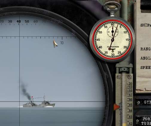 Starting the stopwatch to begin the count The caption then lowers the periscope to avoid detection, and waits until 3 around minutes. During this time, if you have already identified the target, you can set up your torpedo pistol and depth information ready for the shot and maneuver the U-Boat to a more favourable angle if necessary. Just after 3 minutes have elapsed, the captain returns to, and raises, the periscope in preparation for the next mark. Note the display on the stopwatch. 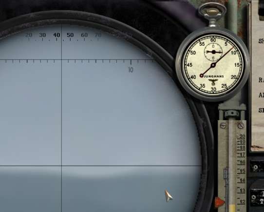 Raising the periscope just before 3 minutes and 15 seconds has elapsed At exactly 3:15, a second point on the map is made, showing the precise point of the target's bow at that time. It can be helpful to switch back to the navigation map a few seconds before 3:15, and manually count the remaining time to ensure that the mark is made as close to exactly 3:15 as possible. 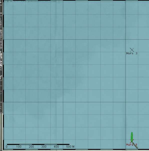 Making the second mark for the plot Just before lowering the periscope once more, the captain may take a bearing to the target, to assist in calculating AOB. He now has all of the information required to calculate the target speed and course. Back on the navigation map, use the Ruler tool to draw a line between the two points we have marked. If you wish to also determine the course, ensure that the extra compass display is turned on by clicking the '?' at the top-right of the screen if necessary. In the example, the distance between the points is 0.7km. Due to us timing over exactly 3 minutes and 15 seconds, we can simply multiply by ten to calculate the speed in knots. In this case therefore, the speed is 0.7 x 10 = 7 knots. The target course can be determined by using the compass display. Always look at the point where the "tail" of the vessel crosses the bearing ring. In this case, the target is heading down the page, therefore the "tail" is crossing at 180°. We have successfully calculated our target course and speed: 180° at 7 kts. 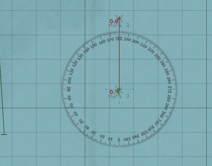 Determining the speed and course |
|
|
|
|
08-25-13, 01:26 AM
|
#6 |
|
Sailor man
Join Date: Mar 2011
Posts: 47
Downloads: 27
Uploads: 0
|
Angle on bow
Angle on bow, or AOB, refers to the angle between a vessel's heading and the bearing of your U-Boat from that vessel. Table of contents [hide] 1 Introduction 2 Setting the AOB 3 Determining AOB 3.1 90° solution 3.2 Visual estimation 3.3 Protractor method 3.4 Calculation Introduction If a crew member on a target vessel stands on the bow of their ship and points one flashlight straight ahead, and another towards your U-Boat, then the AOB is the angle between the two flashlight beams. Note that the AOB is always reported as an angle of less than 180°, port or starboard. Some examples: If your u-boat is directly in front of the target, AOB is zero If your u-boat is directly behind the target, AOB is 180 If a target crewman facing forwards has to look exactly left to see your U-Boat, AOB is port 90° Setting the AOB The AOB can be set via the Notepad, or entered directly into the TDC. Once you have set the AOB correctly at a certain target bearing, you do not need to update it again unless the target changes course. This is because the TDC will automatically adjust the AOB setting as the bearing to the target changes. When entering an AOB, always ensure that the bearing shown on your optics matches the target bearing at the time of determining the AOB. If you are using the Notepad, then once it is set it is a good idea to clear the notepad data, unless you are going to fire without making any further updates for range or speed. Otherwise, submitting the notepad data again later will reset the AOB back to what it was when you first submitted it. As the bearing to the target will almost certainly have changed during that time, the AOB will then be incorrect unless you have adjusted it again yourself in the meantime. Determining AOB The AOB can be determined in several different ways 90° solution If you have maneuvered your U-boat to be perpendicular (ie at 90°) to the target's course, then you can assume a 90° AOB (to port or starboard as appropriate) when the target is directly in front of you (at a 0° bearing in your periscope or UZO.) At AOB values close to 90°, it is not essential to be highly accurate with your AOB value, particularly when attacking at close range. Visual estimation An experienced captain can accurately estimate the AOB of a target purely from sight. The recognition manual has some images that can assist with this task. This is the least accurate of the methods, unless you are very good! Protractor method If you have plotted a future course for the target on the navigation map, then you can use the built-in protractor tool to quickly and easily find the AOB. Take a bearing to the target (this will be used later), and immediately note the position of the target on the navigation map using the Marker tool. If using the Three Minute Rule to determine target speed, then it can be convenient to use the second timing mark for this purpose. In that case, after making the second mark switch immediately to your periscope or UZO view and note the bearing to the target at that time. It is useful to unlock the target from the optics view so that your optics will stay on that bearing for when we need to enter the AOB later. 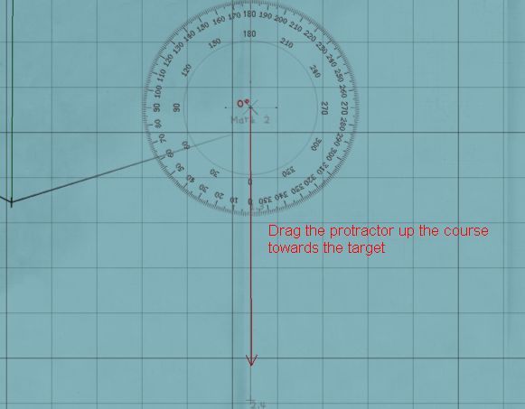 Draw the first line from the target's future course to the centre of the target By making a mark, instead of using the ship icon shown on the navigation map, we remove any confusion caused by the ships movement during the plotting. We can also take a little longer to ensure that the lines are plotted accurately. As long as we know the bearing to the target at the time the mark was made, we can still correctly enter the AOB after any period of time has passed. Using the protractor tool, draw the first line from a position along the target's future course, to the centre of the target. Click once to lock it in, and then draw the second leg precisely to the centre of your U-Boat. Click again to complete the operation. The angle shown on the protractor tool is the Angle on Bow. You can determine port or starboard simply by looking at the location of your U-boat in relation to the target. In this example, the angle is 68°. As we are to the starboard of the target (which is heading south), our AOB is 68° starboard. We can now set our bearing (by rotating the periscope or UZO) back to the value noted at the time of determining the AOB. Once that is correct, we can enter our AOB using either the notepad or directly into the TDC. 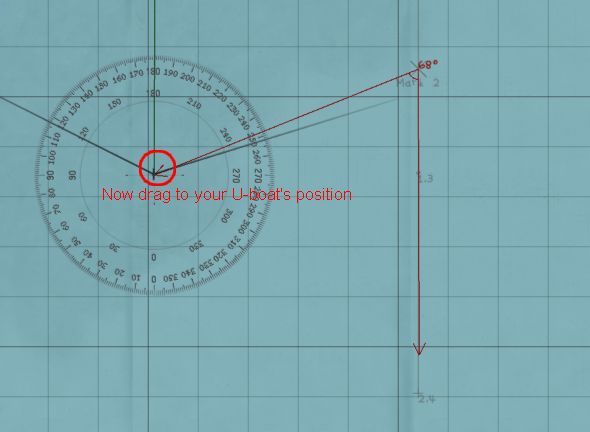 Draw the first line from the target's future course to the centre of the target Calculation If you know the course of the target, as well as its bearing from the U-Boat, then you can accurately calculate the AOB. You must know the True Bearing of the target - that is, the bearing from zero degrees (North), not from your own heading. AoB = Target True Bearing - target course (plus/minus 180° to get the result within -180 to +180°) If the final figure is positive, then the AOB will be to starboard. If negative it will be to port. Note that even if your initial subtraction results in a figure between -180° and 180°, you must still +/- 180°. Some examples: Let's assume a target course of 50°. Depending on the True Bearing to the target, the AOB will be calculated as follows: True bearing Calculation Result 330° 330 - 50 = +280, minus 180 = +100 100° starboard 260° 260 - 50 = +210, minus 180 = +30 30° starboard 140° 140 - 50 = +90, minus 180 = -90 90° port 20° 20 - 50 = -30, plus 180 = +150 150° starboard 230° 230 - 50 = +180, minus 180 = 0 0° Relative Bearing A relative bearing is a bearing taken from the perspective of your own vessel. That is, a bearing of 0° will be directly in front of your U-Boat, and a 90° bearing will be exactly to your right. This is in contrast to a True Bearing which is always measured from zero° (north) and is independent of the direction which your own vessel is facing. Taking a bearing using either of the periscopes or the UZO will give you a relative bearing, as will contact reports from your watchmen or sonar/radar operators. Given a relative bearing and your own course, you can calculate a True Bearing, as shown on that page. True Bearing The true bearing of an object is the bearing expressed as the number of degrees from 0° (north). When using the optics in SHIII, you will see the Relative Bearing, which is the bearing from your own heading, rather than from north. If the U-boat happens to be pointing exactly north (0°) then the True and Relative bearings will be the same. It is possible to convert from relative bearing to true bearing using the following formua True Bearing = Relative Bearing + Own Heading (minus 360 if result is greater than 360) some examples: If the U-Boat is heading at 45° and we are viewing a target in the periscope with the bearing showing as 220° then the true bearing is 220° + 45° = 265° If the U-Boat is heading at 330° and the target's relative bearing is 70°, then the true bearing is 330° + 70° = 400°, minus 360° = 40°. |
|
|
|
 |
| Thread Tools | |
| Display Modes | |
|
|


 Hybrid Mode
