
|
|
SUBSIM: The Web's #1 resource for all submarine & naval simulations since 1997
|
SUBSIM: The Web's #1 resource for all submarine & naval simulations since 1997 |
 06-13-10, 07:53 PM
|
#16 |
|
Grey Wolf
 Join Date: Aug 2005
Posts: 930
Downloads: 23
Uploads: 0
|
The linked video shows what I've done so far using some html techniques. The actual movement of the 'slides' is very smooth compared to how it looks in the video. It's not much but it's all I can offer back to subsim at the moment. I've had this sitting on desktop and just alt-tab out to use it then alt-tab back into SH4. It works fine. The problem is that the images used have been taken from a distance and at a slight angle which throws off the graduations and lining them up thereby affecting the overall accuracy of the digital tool. If Gino can get a clear scan of the device and provide images then this will be a done deal and I'll make it available for all. Having said that, I'm not sure if the graduations on the actual scope are realistic in that they can be used with the omnimeter. I've used this rough version and what the omnimeter was giving me was close to what I saw in the scope graduations but not perfect.
http://smg.photobucket.com/albums/v6...=omnimeter.mp4 Last edited by tomoose; 06-13-10 at 08:12 PM. |

|

|
|
06-19-10, 01:42 PM
|
#17 |
|
Grey Wolf
Join Date: Aug 2005
Posts: 930
Downloads: 23
Uploads: 0
|
I've briefly tested my 'virtual' omnimeter by comparing my TDC data with what the omnimeter shows.
Allowing for the discrepancies caused by the fuzzy graduations on the virtual omnimeter it actually seems to work! Here's what I tried; 1. Get mast height from ID book then slide this figure on the omnimeter. (pause game, alt-tab to my virtual omnimeter slide rule on desktop etc). 2. Get range to target using TDC and stadimeter. 3. Check scope graduation indicated on omnimeter by the combination of the mast height and range data. 4. Check on periscope (high power) to see if marks on periscope match what omnimeter tells me (i.e. omnimeter indicates 2 1/2 graduations on high power on the scope should match the mast height in my scope picture). It seems to work better if the scope marks are set from the main deck to the mast top as opposed to from the surface of the water to the mast top. It seems to work albeit not exact. I've only used high power markings so far as low power doesn't give a good clear indication of the masts at distance (at least on my poor rig). I haven't figured out what the angle on the bow slide is supposed to do as yet. 
|
|
|
|
|
06-19-10, 02:22 PM
|
#18 | |
|
Ocean Warrior
 Join Date: Jan 2008
Posts: 2,909
Downloads: 77
Uploads: 11
|
Quote:
__________________
-------------------------------- This space left intentionally blank. |
|
|
|
|
|
06-19-10, 03:51 PM
|
#19 |
|
Grey Wolf
Join Date: Aug 2005
Posts: 930
Downloads: 23
Uploads: 0
|
So if I set the mast height on the one slide and it indicates (for the sake of an example) 2 on high power.
Then how is the AOB slide used? Is the actual AOB lined up with the high power 2 mark? i.e. if the AOB is 70 then I slide the AOB slider to line the 70 up with...? There is a black arrow at the 90 AOB mark which I'm not sure about either.
|
|
|
|
|
06-19-10, 04:37 PM
|
#20 |
|
Ocean Warrior
Join Date: Jan 2008
Posts: 2,909
Downloads: 77
Uploads: 11
|
Right, it's a bit of guesswork and a bit of science. Which information do you have and what information do you want?
OK, so assuming you know how to use the omnimeter to get the target range from the mast head height and telemeter scale, then what you need to do is to reverse the process to get the foreshortened length in feet of the target based on the angular length. So if the target was at 2,000 yards and it spanned five horizontal graduations on the telemeter, then set 5 against 2,000 and the indicated mast head height is the foreshortened (due to the AoB) target length. Now, if you know what the target length is, then you can set the 90 (with the black arrow) against the known target length (using the range in yards scale) and then where the measured target length in feet is (read as against range in yards) then that's the AoB. Or, if you guesstimate the AoB, or plot it to work out the AoB, you can deduce the real target length by placing the plotted AoB against the foreshortened target length and where the black arrow at 90 is will be the true target length. Target length can then be used with the Torpedo Spread Angle Calculator to work out what spread angles to use.
__________________
-------------------------------- This space left intentionally blank. |
|
|
|
|
06-20-10, 07:07 AM
|
#21 |
|
Grey Wolf
Join Date: Aug 2005
Posts: 930
Downloads: 23
Uploads: 0
|
Thanks Nisgeis. That makes sense. I'll have to play with it some more.
I'm still hoping Gino can get a good scan of the tool so I can use better images for my virtual version which, hopefully, will make the graduations much clearer and therefore more accurate. As I mentioned, I use it on the desktop and just 'pause' and alt-tab out use it then alt-tab back to the game. It works fine that way. I'm still in learning mode and using the game to verify what the omnimeter is showing me and vice versa. Can you confirm whether the mast height in question is from the water surface or from the main deck to the top of the mast. It appears at first blush that the scope telemeter graduations (at least on high power) are more accurate if the height is taken from the main deck. Does that make sense? |
|
|
|
|
06-20-10, 08:22 AM
|
#22 | |
|
Ocean Warrior
Join Date: Jan 2008
Posts: 2,909
Downloads: 77
Uploads: 11
|
Quote:
__________________
-------------------------------- This space left intentionally blank. |
|
|
|
|
|
06-24-10, 02:28 PM
|
#23 |
|
Pacific Sub Expert
 Join Date: Aug 2006
Location: Las Vegas, Nevada
Posts: 148
Downloads: 56
Uploads: 0
|
I just got this reply from the 'keeper' of Cod's Omnimeter:
I've had this thing disassembled for more than a week and have been trying to get suitable images for use in a simulator or general image. The problem is that almost all of the background is either white or aluminum (also white) with the only contrasting component being the tiny black characters and grid lines. My copy app has great difficulty handling this dynamic range, so the result is very poor. Even at 600 dpi much of the grid and much of many character drop outs. I just got the idea of killing off the white scanner background with flat black construction paper and managed to find a source of the paper today. I will be trying it ASAP. It would be appreciated If any of our SUBSIM scanner "experts" can share some ideas. I'll keep at it. Any tips, hints or ideas to tackle this problem?
__________________
Gino |
|
|
|
|
06-24-10, 03:21 PM
|
#24 |
|
Ocean Warrior
Join Date: Jan 2008
Posts: 2,909
Downloads: 77
Uploads: 11
|
Try tilting it at an angle, so that some of the light gets reflected away, rather than toward the scanning head. Try a few angles to see what you get. Any distortion created should then be removable with the perspective tool in photoshop or similar and you'll get a nice square image back. In theory anyway.
__________________
-------------------------------- This space left intentionally blank. |
|
|
|
|
06-27-10, 10:36 AM
|
#25 |
|
Grey Wolf
Join Date: Aug 2005
Posts: 930
Downloads: 23
Uploads: 0
|
Sorry for the late reply, I just moved house and just got phone hooked back up.
How about a flat, non-reflective tracing paper over the surface of the omnimeter to cut down the reflectivity? or matt-finish scotch tape? OR disregard the scanner and try a digital photo from directly above with a high res setting on the camera and a white non-reflective backround if possible. Just a couple of ideas of the top of my head. regards, Tomoose |
|
|
|
|
07-24-10, 10:51 AM
|
#26 |
|
Grey Wolf
Join Date: Aug 2005
Posts: 930
Downloads: 23
Uploads: 0
|
@ Gino;
any progress regarding getting a decent image of the omnimeter? regards, tomoose |
|
|
|
|
07-24-10, 01:33 PM
|
#27 |
|
Pacific Sub Expert
Join Date: Aug 2006
Location: Las Vegas, Nevada
Posts: 148
Downloads: 56
Uploads: 0
|
Unfortunately not. The president of the USS Cod Submarine Memorial is still recovering from surgery. He is also undergoing chemo therapy. So, I will send him another request with the status of the project.
But at this stage things don't appear to be looking well for the photos. Groetjes,
__________________
Gino |
|
|
|
|
07-24-10, 06:24 PM
|
#28 |
|
Grey Wolf
Join Date: Aug 2005
Posts: 930
Downloads: 23
Uploads: 0
|
Gino;
roger that. Let's not bother him on this then, he's obviously dealing with a lot of much more important RL issues. The omnimeter stuff can certainly wait. I've tried searching online and surprisingly this site (subsim) is the only place where there's any real mention of the omnimeter (I'm including the links to the historical naval site). You'd think there'd be more out there somewhere but nothing. |
|
|
|
|
08-19-10, 12:33 PM
|
#29 |
|
Grey Wolf
Join Date: Aug 2005
Posts: 930
Downloads: 23
Uploads: 0
|
Given the situation as outlined in the last posts I'm turning to the subsim community at large to see if there's any other sources out there that have access to the metal omnimeter or good pictures of one that they can post and I can in turn convert to an html version useable during the game. I have the programming part done and a working prototype exists (you just click and drag the sliders) using the graphics available so far but due to the 'angle' of the photos it just doesn't look right so any pics/photos/diagrams that clearly show the graduations would be most appreciated.
Thanks in advance.
|
|
|
|
|
09-02-10, 11:21 AM
|
#30 | |
|
Admiral
 
Join Date: Apr 2005
Location: Dayton, Ohio
Posts: 2,292
Downloads: 474
Uploads: 64


|
A goal of mine has been to accurately preform manual targeting duties using instruments like the Omnimeter. I made the "Angle on Bow Calculator" to do just that when this game was released. It helps in finding target bearings and headings when certain known factors are used. In my opinion, the Omnimeter can help in several ways to find range to target and AoB by just using the scope's Telemeter markings and calculating the relationship between what you see and the true measurement of the targets height and length. To this end I wrote Gino to help in what he had regarding the Omnimeter.
As this post leads off, his assistance of the images of the U.S.S. Cod's Omnimeter was greatly appreciated. The referenced use of the Omnimeter can be found HERE in the United States official document called "Submarine Torpedo Fire Control Manual", dated May, 1950. The document has been invaluable in determining what the real life scopes "field of view" and "magnification" should be to accurately give figures for the Omnimeter to use. Scroll down to Chapter 5 to find how the "range omnimeter" is used (by the way, the "Approach Officer" is you, the Captain). I do admit, some of the figures the manual uses are inaccurate when you do the math!! Who the heck were the proof readers for these kinds of manuals!?! I'm getting a bit ahead of myself, but it's safe to say the games optics are not correct and will not produce a correct figure for an authentic tool as the Omnimeter to use. This isn't surprising considering the mast head heights used in the game are off target as well (that was why I created SCAF, to correct height figures at key reference points). Anyway, my first task is to create a working Omnimeter in-game then calculate the correct "field of view", magnification, then find the correct ship length similar to finding the correct height and adding it to the Recognition Manual. I'll combine the SCAF height figures to allow the player to use a set of Length and Height figures for each ship to accurately use the Telemeter scope marking and Onmimeter to figure Range and AoB. This first task is complete. The following images show a circular Omnimeter which can be pulled out/in with the "Attack Data Tool". The two working dials (both having the lighter grey color) can be manipulated separately with little interference from other dials. The outer A.O.B. dial is moved with the use of the Attack Data Tool AoB dial. Just mouse drag the AoB dial. The inner Telemeter High/Low Power scale dial can be moved by mousing the Height / Length area of the dial. This is an image of the game at the standard 1024x768 resolution: 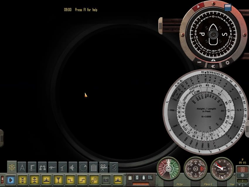 This is with a resolution of 1280x1024: 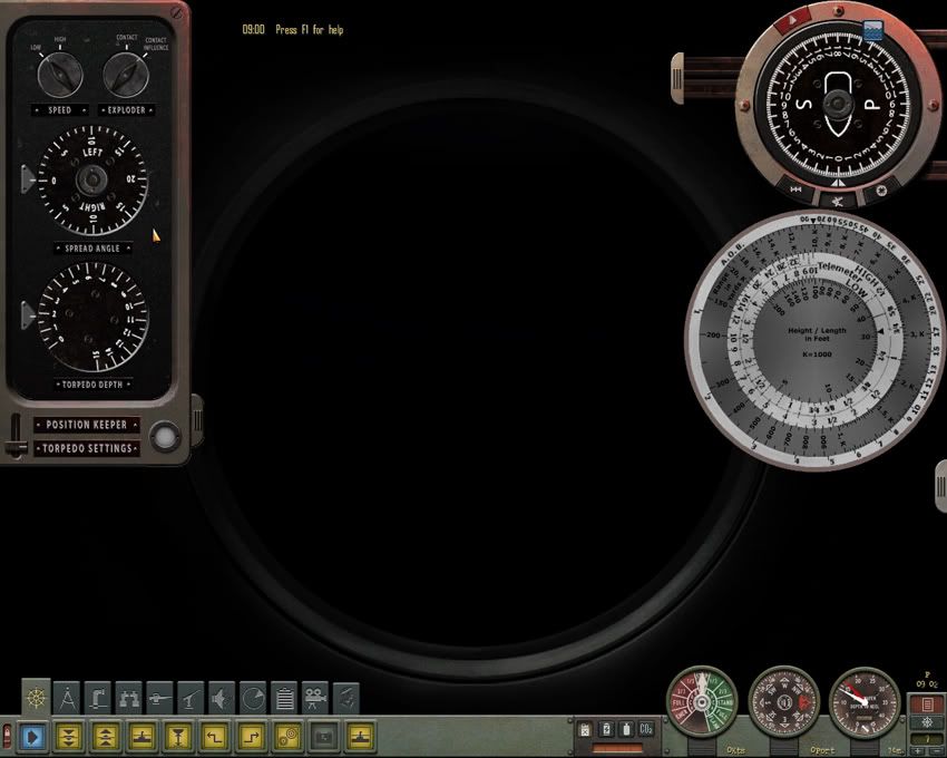 I think the size I'm using is the best compromise for the game resolutions we're given. Needless to say, there's still work to be done. Going over all ships to find correct length will take some time but the placement of an Omnimeter in-game is the biggest part now out of the way. I'm planning on calling the modification "Manual Targeting Assist". I'll be putting a WIP thread together soon to go over what I'm doing. Best regards.
__________________
 The HMS Shannon vs. USS Chesapeake outside Boston Harbor June 1, 1813 USS Chesapeake Captain James Lawrence lay mortally wounded... Quote:
Last edited by CapnScurvy; 09-03-10 at 03:26 PM. |
|
|
|
|
 |
|
|


 Linear Mode

