SUBSIM Radio Room Forums


SUBSIM: The Web's #1 resource for all submarine & naval simulations since 1997

Go Back   SUBSIM Radio Room Forums > Silent Hunter 3 - 4 - 5 > Silent Hunter 4: Wolves of the Pacific
Forget password? Reset here

Reply
 
Thread Tools Display Modes
Old 05-08-13, 07:26 PM   #46
TorpX
Silent Hunter
 
Join Date: Sep 2010
Posts: 3,975
Downloads: 153
Uploads: 11
AFS II (continued)

Final Form:


After I got the basic solution equations, I spent some time checking the math by computing the answers to a few sample problems and plotting the results on graph paper to verify the the answers are correct, and not just a heaping pile of algebraic missteps. Then, I went back to the equations and multiplied out the terms to look for ways to simplify the equations, or at least, put them into a more pleasing form. I was able to use trig reduction formulas in a few areas, but could not really make any major simplifications. I also put the trig functions in terms of the track angle and added a factor, Lg for what I call “launch lag”, as experiments indicated that this was greater than I had expected.


Residual problems:


Most of my work now is on developing a program that will do these calculations and some other auxiliary tasks to make this method a practical proposition. As I said before, the equations for t1, t2, and t3 are the core of this method. It is not immediately obvious, but the denominators of the expressions for t1, and t3 can be zero, resulting in either or both of t1 and t3 being undefined. If these cases were all “no-solution” cases, this wouldn't be a problem, but I found this not to be the case. For example, if the sub is heading north and the target south, on tracks that coincide, go = 0, t1 is undefined, though clearly a solution exists! On the other hand, if sub and target are heading in opposite directions, as before, but on parallel tracks, t1 is undefined, and no solution exists. I spent quite a bit of effort trying to sort through these cases of “parallel tracks”, in an effort to separate the wheat from the chaff. Then it occurred to me that there was a much better way.


I arranged the program to calculate t1 and t3, if they are defined. If t1 is undefined, t1 is set to zero, and passed to the calculation of t3, to check if this will yield a solution. If t3 is undefined, the alternate equation is used. Then the provisional solution is checked by adding up the positions of target and torpedo through each phase, so that the final position coordinates can be compared. If they match up, the solution is considered valid, if not, it is rejected. Easy!


Still to do:


I still have quite a lot to do on the AFS II program. The basics are in place, but a lot of details and refinements are not done. I think I have the torpedo data for the Mk 10 pinned down pretty well, but haven't started on the Mk 14 yet. I might try to compile data for one or two German torpedoes, later.


I'll be posting some sample problems in the near future, to illustrate the method.

I'm sure there are some aspects of this that aren't entirely clear, but I'm not sure how far into the weeds people want to get. If anyone has any questions, I'll do my best to answer them.

Edit: I forget to mention that all these equations are for arbitrary units; that is distance in length units, time in time units, speed in length/time units. The reason for this is, that it is much easier to check the math this way.


TorpX


P.S. If anyone can give me some tips on getting equations and formulas display in a proper manner, I'd be grateful. Using the Paint program was not my first choice, but I couldn't get the math to display well in wordpad.

Last edited by TorpX; 05-09-13 at 07:22 PM. Reason: added note at end about units
TorpX is offline   Reply With Quote
Old 05-09-13, 12:49 PM   #47
Dorjun Driver
Loader
 
Join Date: Jul 2012
Location: The Upper Left Edge
Posts: 81
Downloads: 77
Uploads: 0
Default

Oh, goody!
Dorjun Driver is offline   Reply With Quote
Old 05-09-13, 05:05 PM   #48
Gilead Abyss
Watch
 
Join Date: Oct 2012
Posts: 17
Downloads: 9
Uploads: 0
Default impressive

A very impressive exercise so far, and I've enjoyed (really!) following the thought process and problem-solving.

I hope you are able to code this together into a working tool, but even if that stumps you, this has really added to the sense of longhand pencil work needed to make these weapons at all effective.

Here's hoping this proves to be more than an exercise for you.

Well done
Gilead Abyss is offline   Reply With Quote
Old 05-09-13, 08:00 PM   #49
TorpX
Silent Hunter
 
Join Date: Sep 2010
Posts: 3,975
Downloads: 153
Uploads: 11
Default

Thank-you for your kind words.

I can promise you that I will release a program that will do these calculations and put this concept into practice. It may not fulfill my ambitions 100%, but will get the job done. Someone on the forum said, it was customary for 80% of the coding to be done in 80% of the time alloted, with the remaining 20% being done in the other 80%. Based on my personal experience, I would go along with that.

One thing I decided to incorporate, is a "sketch" function where you can have a window pop up with a graphical representation, of the solution just computed. I have it working now, but would like to polish it some more. Anyway, I'm excited about it. I think people will find it worthwhile.

Quote:
...longhand pencil work needed ...
And there was plenty of that, I can assure you.

My first attempt I threw out because I had the X-axis accross and half-way into it, I realised it was a mistake, and I needed to start over. The second attempt, I discarded because I was trying to make multiple algebra steps in each line and some mistakes had creeped in. I decided it was best to start over... I had to use blank paper turned sideways so I could fit the equations on one line. It made me wish I had some really large chalkboards to use.
TorpX is offline   Reply With Quote
Old 05-10-13, 08:22 AM   #50
Gilead Abyss
Watch
 
Join Date: Oct 2012
Posts: 17
Downloads: 9
Uploads: 0
Default

Quote:
Originally Posted by TorpX View Post
to incorporate, is a "sketch" function
This is a great idea! A quick visual inspection to make sure I'm getting an answer to the question I think I'm asking.

Some folks can read equations and translate to "picture ideas" on the fly. For the rest of us, this is a brilliant way to provide a quick double-check.

Again, impressive work. Thanks for sharing.
Gilead Abyss is offline   Reply With Quote
Old 05-10-13, 09:54 PM   #51
TorpX
Silent Hunter
 
Join Date: Sep 2010
Posts: 3,975
Downloads: 153
Uploads: 11
Default

Quote:
Originally Posted by Gilead Abyss View Post
Some folks can read equations and translate to "picture ideas" on the fly. For the rest of us, this is a brilliant way to provide a quick double-check.
Exactly. It is very easy to input a gyro angle of 85, when you needed to input -85, or use a track angle of 70, instead of -70.
TorpX is offline   Reply With Quote
Old 05-15-13, 10:13 PM   #52
TorpX
Silent Hunter
 
Join Date: Sep 2010
Posts: 3,975
Downloads: 153
Uploads: 11
Default

I've put together a few examples so people can look at some specific numbers, and check the math if they so desire.

Ex. A1
track angle : -120
gyro angle : 40
sub speed : 2
target speed : 6
target range : 1200
target bearing: 55 deg.

torpedo config:
torpedo speed: 20
q : 120 'torpedo reach
r : 100 'turning radius
Lg : 4 'launch lag
bb : 30 'bow tube distance

Note that all figures are in coherent units; i.e. ranges in meters, times in seconds, and speeds in meters per second. This makes checking the math much easier. Of course, in the finished program, speeds will be in knots.

start readout
Kd 0.26146582 'sub functions
Kx 18.0519046
Ky 12.3208889
Kz -118.17693
Px 222.278761
Py 23.3955557
TT 1 'torpedo tube status, 1= bow, -1= stern

t1 22.1297521 'time intervals
t2 13.4906585
t3 42.90395

T0x 688.291724 'x and y coordinates of sub, target, and torpedo
T0y 982.982453
T1x 754.68098
T1y 867.992888
T2x 795.152955
T2y 797.89337
T3x 923.864805
T3y 574.957907
U1x 44.2595041
U1y 0
U2x 71.2408212
U2y 0
U3x 157.048721
U3y 0
P2x 266.538265
P2y 23.3955557
P3x 923.864915
P3y 574.958105

tgt bearing at launch: 50.7008883
tgt bearing at impact: 36.8625251

Torp Track 1047.89217
Error: 0.22621151e-3 'error between computed torp and target positions
Ath1: 5.23598776 'relative target heading, radians
in deg.: 300
Abg1: 0.95993109 'relative target bearing, radians
in deg.: 55
Agyo1: 0.6981317 'gyro angle, order, radians
in deg.: 40

At t = 0
target is at T0
sub is at U0
sub computes firing solution

At t = t1
target is at T1
sub is at U1
sub launches torpedos

At t = t1 + t2
target is at T2
sub is at U2
torpedo is at P2
torpedo has finished turn

At t = t1 + t2 + t3
target is at T3
sub is at U3
torpedo is at P3
torpedo impacts with target

see below


In Ex. 2, all initial sub, torp, and target data is the same except the gyro angle is 0.

start readout
Kd -10.9451942
Kx 5.19615242
Ky 17.0
Kz -103.923048
Px 158
Py 0
TT 1

t1 138.093638
t2 10
t3 41.0810475

T0x 688.291724
T0y 982.982453
T1x 1102.57264
T1y 265.426863
T2x 1132.57264
T2y 213.465339
T3x 1255.81578
T3y 0.1954525e-2
U1x 276.187275
U1y 0
U2x 296.187275
U2y 0
U3x 378.34937
U3y 0
P2x 434.187275
P2y 0
P3x 1255.80823
P3y 0

tgt bearing at launch: 17.8065083
tgt bearing at impact: 0.1276243e-3

Torp Track 941.62095

Error: 0.7802254e-2

Ath1: 5.23598776
in deg.: 300
Abg1: 0.95993109
in deg.: 55
Agyo1: 0
in deg.: 0

This shows the math works just as well for 0 gyro angle shots.


In Ex. 3, again, everything is the same except the gyro angle is -20. This gives a less favorable track, but might be necessary if you had to delay your launch for some reason.

start readout
Kd -13.8806698
Kx -1.64425044
Ky 15.7938524
Kz -77.1345132
Px 192.202014
Py -6.03073792
TT 1

t1 193.104632
t2 11.7453293
t3 45.8665896

T0x 688.291724
T0y 982.982453
T1x 1267.60562
T1y -20.4186501
T2x 1302.84161
T2y -81.4491711
T3x 1440.44138
T3y -319.778962
U1x 386.209265
U1y 0
U2x 409.699923
U2y 0
U3x 501.433102
U3y 0
P2x 578.411279
P2y -6.03073792
P3x 1440.42119
P3y -319.776689

tgt bearing at launch: 358.672909
tgt bearing at impact: 341.193741

Torp Track 1072.23838

Error: 0.20310576e-1

Ath1: 5.23598776
in deg.: 300
Abg1: 0.95993109
in deg.: 55
Agyo1: 5.93411946
in deg.: 340.0


I'll post some examples which show the details of the torpedo turning better. The sketches don't really allow you to see the turning part very well, unless you are zoomed in pretty close.

TorpX
TorpX is offline   Reply With Quote
Old 07-21-13, 12:14 AM   #53
TorpX
Silent Hunter
 
Join Date: Sep 2010
Posts: 3,975
Downloads: 153
Uploads: 11
Default

Here is a long overdue update on the program I'm working on.

I've mainly been working on the program itself, but just recently have started some actual firings against moving ships. Anyway, almost all the basic elements are in place, I have the "sketch" function all done, apart from last minute tweaks, and I hope to start making final math checks fairly soon.

The program will enable the user to produce "sketches" like these:

This first one shows how the torpedo track will look if you are zoomed in close enough. I've used a larger value for the turning radius so you can see it better. In most cases, you will be making shots at a longer range and not using a 180 degree gyro angle (I hope ), so the curve of the track will appear abrupt. However, I wanted it to provide a good representation of the solution and have put in a lot of work on this aspect of the program. As you can guess, I've been having a little fun with it. You can compute solutions that your torpedoes cannot perform; there aren't any hard-coded limits built in.


The next shot shows what a more typical solution might look like. I used the same torpedo data with this set up. The curvature of the torpedo track is much less noticeable.


This last shot shows how it can be used to create a graphical record of an attack. I had to redo much of the code for the drawing portion, so the orientation of the sub can be changed. Before, the sub was always shown to be headed straight up toward the top. I still think the default heading is best for guaging angles and such, but for making a record, or comparing it to the SH4 charts, it is nice to be able to reorient the sketch.


Note that everything shown here can be put on the chart without outside "post-production" tools like Paint or such. Of course, you can calculate the solution without using the sketch function at all. Originally, I had it in mind to do just that, but the more I thought about it, the more I wanted to implement it in some way. It required quite a bit of effort before I was satisfied with it.

I need to do some more of the shooting gallery stuff, but I do not plan to conduct a mind-numbing number of tests. I have a good deal of confidence in the underlying math; I only need to refine the values associated with the torpedo reach, turning radius, and such. Right now, this is my biggest problem. I know the values I'm trying now are close, but not exactly a match. I thought I could tease out the numbers with various tests, but there are limitations with this approach. The in-game TDC only reports gyro-angles to the nearest degree, and shooting at moving ships is not exact, since they try to dodge the torpedoes. I will probably have to settle for values that are "close", and not quite spot-on. In any case this is the last big hurdle to finish.
TorpX is offline   Reply With Quote
Old 07-23-13, 08:37 AM   #54
c13Garrison
Ensign
 
Join Date: Jul 2013
Location: Chicago-ish, USA
Posts: 223
Downloads: 14
Uploads: 0
Default

After reading this thread, I am reminded of what I enjoy when reading about WWII hardware. Not just a rote repetition of facts, but rather the stories behind the engineering decisions that were being made. To wit, I would LOVE to read the original notes on the first hash-out round-table session over the design of the TDC. Real mechanical engineering.

But BTW- Awesome programming work. You clearly have a zeal for this sort of thing.
c13Garrison is offline   Reply With Quote
Old 07-24-13, 12:30 AM   #55
TorpX
Silent Hunter
 
Join Date: Sep 2010
Posts: 3,975
Downloads: 153
Uploads: 11
Default

Thanks.

I have gotten better at this. (This isn't really saying much, though.) I'm sure someone who was really good at this sort of thing could have finished it in a quarter of the time it has taken me.

I'm getting anxious to finish it, and go on patrol and give it a "field test".

I just put together a small program that tabulates values of Gyro angle Vs. Bearing angle, so I could more easily check combinations of torpedo reach, turning radius, and such. I am hopeful of getting more accurate results now. I'll do some more testing tomarrow.
TorpX is offline   Reply With Quote
Old 07-26-13, 12:44 AM   #56
TorpX
Silent Hunter
 
Join Date: Sep 2010
Posts: 3,975
Downloads: 153
Uploads: 11
Default

I did a little testing with the Mk. 14 torpedoes. As far as I can tell, they have the same reach and turning radius as the Mk. 10's. That makes things a little easier for me. They do have a greater lag; that is they take longer to exit the tube.

I also did some testing of torpedoes launched from deep submergence, up to 200 ft., and the results agree pretty well with the stated "max dive angle" listed the the game files. This isn't a major deal, but I wanted to put this into the solution model, so if anyone wants to try sonar only attacks, they can. I know the RL Mk. VIII Angle Solver had different plates for different depths.
TorpX is offline   Reply With Quote
Old 10-19-13, 12:47 AM   #57
TorpX
Silent Hunter
 
Join Date: Sep 2010
Posts: 3,975
Downloads: 153
Uploads: 11
Nearly Finished!

Since the new firing solution program is nearly ready for release, I thought I'd show the math for some of the auxiliary functions/tasks.

This is the Gyro Angle Setting calculator. Since there is currently no way to set the torpedo gyro angles directly (at least in the USN side), it is necessary to calculate a bearing, whereby the TDC mechanism, will be forced to set the gyro angle you want. This is the most important of the Auxiliary functions in the program since it will be required for most launches.


In the above diagram,
b is the distance from the periscope/TBT and the end of the torpedo tubes
q is the torpedo's reach, (distance traveled before turning)
r is the turning radius
n is the difference between b+q and the location of where the torpedo track, extended backwards, intersects the sub track
R is the range input
g is the gyro angle
theta is the bearing angle
B is the difference between g and theta

g0, in the last equation, is the gyro angle, order; the gyro angle indexed from 0 to 360 deg.


Note that the red 'X' is not a target ship, but an arbitrary point the the TDC is pointed to, to achieve the desired gyro angle.


Next up is the Torpedo Spread calculator:


This enables the user to compute a divergent spread after the firing solution has been computed.

The linear displacement is the sum of three things:
  1. the torpedo track displacement
  2. target displacement
  3. spread displacement
The 1st is due to the movement of the sub and the angles of the torpedo track intersecting the target track. In other words, the projection of the torpedo track along the target track, as the sub moves. If the sub was not moving or the gyro angle was zero, this quantity would be zero.

The 2nd is due to the movement of the target. It is the distance the target moves in the interval between the launch of the next torpedo.

The 3rd is simply the displacement along the length of the target. It depends on the length of the target and how much "coverage" is desired.
In the above diagram:
Dp is the torpedo track displacement
Dt is the target displacement
Ds is the spread displacement

Vu is sub speed
Vt is target speed
k is constant to convert knots to ft./sec.
ti is time interval
f is fractional coverage, expressed as a percent
ln is target length

D is the total displacement

g is the gyro angle
TTa is the torpedo track angle
Z is the adjusted track range (distance of straight run)

d is offset angle, or spread angle

Using this type of spread in a set-up like that shown above, the first torpedo would be aimed near the stern, and each successive launch would be given a larger offset angle going left.


TorpX is offline   Reply With Quote
Old 10-20-13, 02:27 AM   #58
TorpX
Silent Hunter
 
Join Date: Sep 2010
Posts: 3,975
Downloads: 153
Uploads: 11
Default

Here is an illustration of the Aob from Aspect Ratio function:

I don't go into all the finer points of the math, but the diagram gives you a sense of the concept.

With the formula,
l is target length
h is target height
lo is observed length
ho is observed height

W is width
W' is adjusted width

J is a function which compensates for width (or beam) of target

If ships had no width, you could calculate the Aob without J, using the formula with the first term only. J was determined by using only 1 specific model. I considered trying to use different models where you could choose the most appropriate one for your situation, but decided this was more trouble than it's worth.

The ship model was based on the target having a beam equal to 1/8 of it's length. The stern having a radius of curvature equal to 1x the beam, and the bow having a radius of curvature equal to 3x the beam.

The difference between W and W' is zero at Aob's between 60 and 120 degrees, and is still very small between 30 and 150 deg. At Aob's close to 0 or 180 deg., it becomes important. The value of J is determined by using the formula

m * AR + b
where m and b are selected according to which of 4 zones the AR fall into.


The Timing by Wire function:

Ordinarily, timing by wire is done with the periscope at 0 deg., and pointing the sub at a location just ahead of the target ship to time the transit across the scope reticle. This allows for a simple calculation where the projected "wire" does not move on the target's track.

However, if we apply some geometry to the problem we can obtain the same information at other angles.

With the formula shown,
Vt is the target's speed, kts.
Vu is the sub's speed, kts.
ln is the target's length, ft.
t is the transit time, sec.
Aob is the Angle on the bow, deg.
theta is the relative bearing, 0 to 360 deg.
k is a conversion factor, ft./sec. to knots

If theta or Vu are zero, the 2nd term, Vu * (sin theta/sin Aob), drops out leaving us with the simplified method mentioned earlier.

The formula is obtained by using the law of sines, and noting the wire's location projected on the target track moves n distance, as the sub moves m. The triangle gets smaller, but the angles do not change.

The form of the equation may seem odd, with the subtraction of the second term, but the signs will work out right, and give the correct answer, provided one is careful to input the bearing as read off the scope, 0 to 360 deg., and input the Aob from -180 (port) to +180 (starboard) degrees. [Either or both the sine of theta, or sine Aob can be negative.]


TorpX is offline   Reply With Quote
Old 10-24-13, 03:56 PM   #59
TorpX
Silent Hunter
 
Join Date: Sep 2010
Posts: 3,975
Downloads: 153
Uploads: 11
Tracking Party 1.1 is Released!

No replies yet. I'll just assume this means people are frozen in anticipation, lol.


Tracking Party 1.1 is released, and available in the downloads section under Utilities:


http://www.subsim.com/radioroom/down...o=file&id=4236


Here I'll provide a tutorial fully explaining the use of the program/method.


Installation:
When you unzip the file, you should have a folder with:

Tracking Party 1.1.exe
Tracking Party 1.1.tkn
3x .SLL files
5x .DLL files
2x .wav files
1x .ico icon
1x Save folder (empty)
1x images folder (17 .bmp files)
this help file


Simply move the folder, with the inside files/folders as-is, to the location of your choosing. I put mine in a folder named SH Auxiliary, but it doesn't really matter, as long as you know where it is, and can reach it. Then make shortcuts from the Tracking Party 1.1.exe, and this help file, and put those on your desktop, or wherever you want them. That's it, you're done! The first time you run Tracking Party, it will create a config. file that stores the display, unit system, and realism settings, and a torp cofig. file that stores the torpedo performance numbers. These can be edited from the menu dialog panels when the program is running.


Configuration:


There are 5 items at the top of the main window that can be accessed to change the various elements of the program.


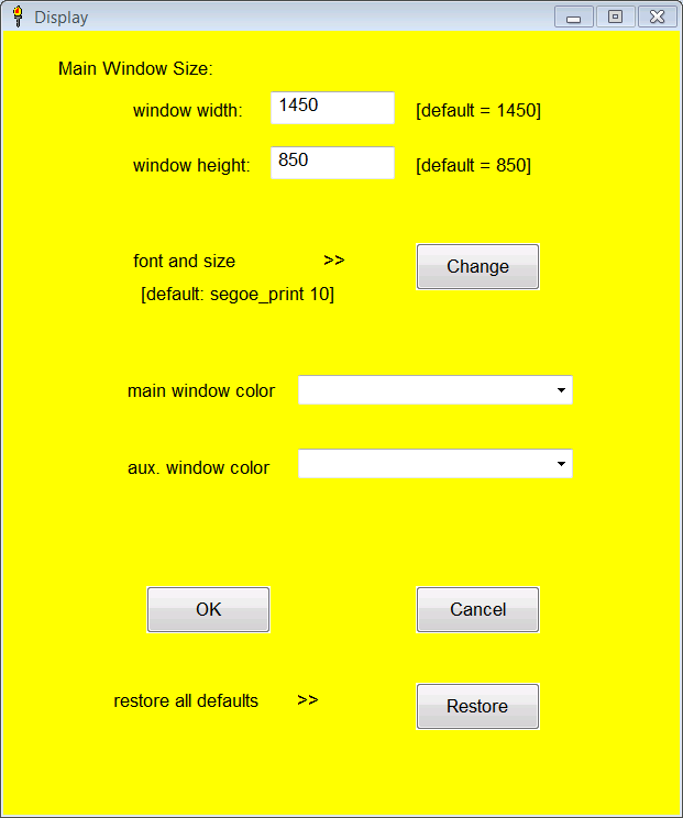
Display - calls up a display config panel where you can change the main window size and color scheme. The auxiliary window's color can also be selected; the size will be proportional to the main window size. Also, a different font and size for type can be chosen. (This is necessary if, say, you want to have a smaller window.) The default font is Segoe_print 11, but this font is not very readable at the smaller sizes, so you might want to use something else if you want a small window. Don't be afraid to play around with the display; you can always easily restore the default configuration, if the display gets messed up. The colors of the main and auxiliary windows can also be changed.


Unit System - changes displayed units of length from english to metric. Defaults to english.


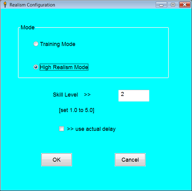
Difficulty - allows selection of either "Training Mode" or "High Realism Mode". There is a selectable crew skill level, delay factor. These are only relevent in the High Realism Mode. The program defaults to Training Mode. The details of the High Realism Mode are explaned below. Defaults to Training Mode.


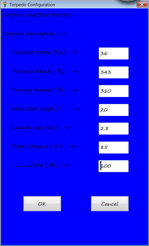
Torpedo Configuration - allows torpedo performance parameters to be edited. These include speed, reach, turning radius, bow and stern tube distance, maximum dive angle, and launch lag. The max. dive angle only comes into play if torpedoes are launched from deep submergence. The stern tube distance for the default S-18/Mk. 10 torpedo combination is an untested guess, as the SH4 version of the S - class has no stern tube.


About - self explanitory.


The program stores any changes made to a file, so it remembers your selections and there is no need to configure it each time you start it up. If the files are deleted, or corrupted, the program recreates them.


Main Window:

Here is the core of the program where the torpedo firing solution is calculated and displayed. The 8 textboxes in the top half of the window are where the firing data is entered into the program. The bottom half is where the computed firing solution is displayed. The 5 buttons at the top right control the flow of the program.
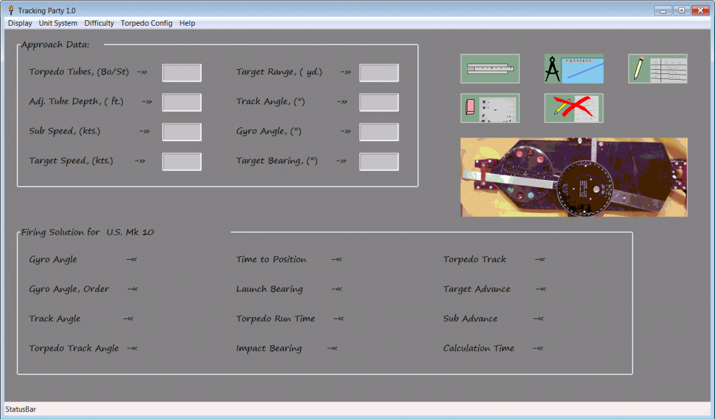


Data boxes:

1. torpedo tubes - bow or stern. If nothing is entered will default to bow.

2. adjusted tube depth - the distance the torpedo must climb to reach set depth. Defaults to 0. Not normally important.

3. sub speed - self explanitory.

4. target speed - self explanitory.

5. target range - self explanitory.

6. track angle - the angle formed from the target's path ahead, to where the sub's path intersects. Can be either negative (port) or positive (starboard).

7. gyro angle - the angle set on the torpedoes; i.e. how much the torpedoes turn. Can be either negative (left) or positive (right).

8. target bearing - self explanitory.


Solution spaces:

1. gyro angle - restatement of gyro angle entered.

2. gyro angle, order - gyro angle indexed from 0 to 360 degrees.

3. track angle - restatement of track angle entered.

4. torpedo track angle - the angle formed by the target's track ahead measured to the torpedo track. Can be either negative (port) or positive (starboard).

5. time to position - the time in seconds for the sub and target to reach the computed firing position.

6. launch bearing - the relative bearing the target should reach for torpedo launch. This is the most critical element of the solution.

7. torpedo run time - the time required for the torpedo to reach the target from launch to impact.

8. impact bearing - the relative bearing the target will reach when torpedoes impact, assuming the sub does not change course.

9. torpedo track - the length the torpedo actually must travel.

10. target advance - the distance the target travels from the plotted refrence point to launch. Displayed mainly to aid plotting.

11. sub advance - the distance the sub travels from the plotted refrence point to launch. Displayed mainly to aid plotting.

12. calculation time - the time required for the "crew" to compute firing solution.
Only relevent in High Realism Mode.


Buttons:

Slide rule (upper left of group) - calculates firing solution.

Eraser (lower left of group) - clears data and results.

Devider/Chart (upper middle of group) - opens up window where sketch of firing is made. Allows user to edit and save sketch of attack approach.

Red cross (lower middle of group) - shuts down program and all windows.

Pencil and worksheet (upper right of group) - opens up window for auxiliary calculations.

Large button - flips image from Mk. VIII Angle Solver (in box) to functional diagram. Has no effect on program execution.


Auxiliary Window:

The auxiliary window allows different calculations to be made in one window. On the right there are 5 textboxes for the input of data, 1 or 2 boxes for output and a single button for run the calculations.

The left side has a list box with the different types of calculation options. Below this is a large button that has a diagram which changes when different calculation options are selected. The small button at the bottom left closes the window.
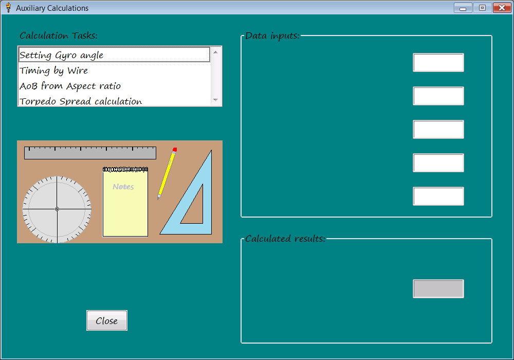


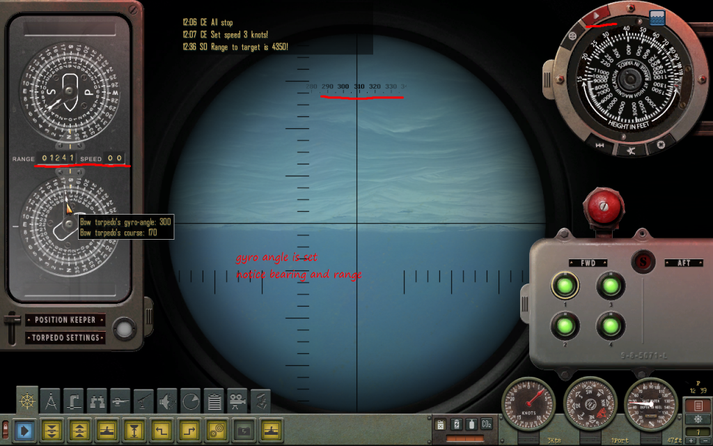
Setting Gyro angle - This is the most important aux. function. It allows you to set the torpedo gyros to an arbitrary value. The tubes used (bow or stern) are input in the first box, the gyro angle desired in the second. The third box isn't used for input, but only displays the gyro angle, order (not really required). The fourth box is the range setting. This is not the range to target, but the range on the TDC dial when the bearing is transmitted to the TDC. The fifth box is a place holder to remind the user that the calculation also uses the torpedo parameters stored in the Torp config. file. If there was some way to set the torpedo gyro angle directly, this function would not be needed, but alas, there doesn't seem to be one in SH4. In stock SH4 the longest range one can input into the TDC without a target selected is 1,241 yds. It is porbably best to use the longest range possible. If you desire to make a zero angle gyro shot, this process is unneccessary.

For example: if you desire to use a -40 degree gyro angle with a Mk. 10 torpedo (S- class) and input a range of 1241 yd. , the program returns a bearing of 325.4 degrees. So after putting 1,241 yds. on the TDC dial, (target speed should be zero), turn the periscope/TBT to 325.4 deg. and hit the red button. This forces the unit to change the gyro angle to -40 deg.


Timing by Wire - This allows you to estimate the target's speed by measuring the time it takes to cross the periscope reticle. Target length, time, sub speed, bearing, and Aob are input. Note that Aob can be either positive (starboard) or negative (port).

Example: a 375 ft. ship takes 22 sec. to cross the wire. It has a -75 deg. Aob at bearing 55 deg. and the sub is moving at 2.5 kts. The target is estimated to be traveling at 12.2 knots.


Aob from Aspect Ratio - The program uses actual target length, height, and observed length and height. The observed length and height can be the reticle marks on the periscope/TBT or any arbitrary unit as long as they are the same value (degrees or milliradians, for example). The program uses a mathematical model that takes into account target width making Aob estimates near 0 or 180 degrees more accurate.

Example: A target of 375 ft. length and 95 ft. height, has an observed length of 8.0 milliradians and an observed height of 3.5 milliradians. An Aob estimate of +/- 35 or +/- 145 degrees is returned. (One cannot determine which is correct by aspect ratio alone; by seeing which end is the bow and observing the direction of travel, the correct value can be selected.)


Torpedo Spread calculation - The program uses target length, spread fraction (expressed as a percentage) and the launch interval to calculate a divergent angular spread. As the program requires solution data, the calculation must be done after a firing solution is computed. The number returned is the angular spread (positive or negative) to be used between each torpedo. This is more fully explained in a comprehensive example later.


Optimum Track angle - Uses target speed and torpedo speed to calculate optimum track angle as defined by USN. This is more for player information than any specific requirement.


Sketch Function:

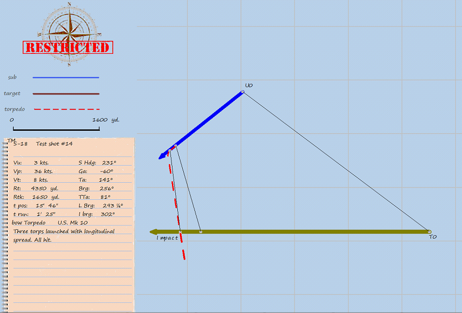
After you enter all the appropriate firing data, and calculate a firing solution, you may want to sketch out the approach and solution to see what it looks like, and verify that the angles and data are what you intended. This is easily done just by hitting the sketch button. The program will automatically draw out the target track, the sub track, and the torpedo track from the input reference point. The signal points, T0, T1, T3, U0, U1, U3, and P3 are indicated, as are the bearing lines between them. Additionally, the firing data and solution are written on a "notepad", and comments or changes can be made by the user. The whole drawing, with any writing or drawing made by the user, can be saved into a file for a permanent record. The window has a legend and scale in yards (or meters). Grid lines are in 1,000 yds. or m.
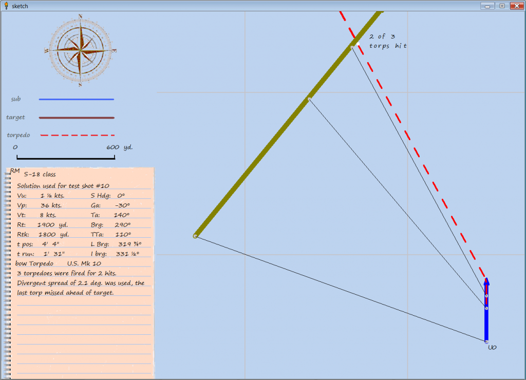


Here are the controls used in the sketch window:

Ctrl + R Redraws sketch so orientation can be changed. Default sketch will always have sub heading north.

Ctrl + T Text boxes activated. Allows user to write in space provided in notepad. After typing out whatever one wants to write Ctrl W
must be used to finish task.

Ctrl + W Writes what user input into text boxes. Must put cursor outside text box to shift focus back to window first.

Ctrl + Z Undo for drawing items in window.

Ctrl + S Saves drawing to bitmap file.

Mouse left button Draws line on sketch.

Mouse right click Allows typing characters at location of cursor. Good for labeling of drawn items for clarity.


Note that the limitations of the programing language make for less than ideal spacing of characters when written on drawing. It is best to write out comments and such in the text boxes where the font is properly spaced.

Sometimes the points where the torpedo impacts and where the target ship are supposed to meet, do not match up exactly. There is no need to be concerned about this. It is merely a limitation in the way the language measures and draws angles. I had to compromise between getting the display in the style I wanted, and drawing precision. It is important to understand that the solution numbers are used to make the drawing, not the other way around. In other words, the numerical solution is much more precise than the drawing.

When you save a sketch, it will be in the Save folder of your installation (in bitmap form). You can, of course alter it later and/or convert it to another file format. I added a "RESTRICTED" stamp and sound effect, so you know the file has been saved.


General Issues:


Probably the most likely area for confusion in entering data would be the gyro angle or track angle. The mathematics behind this method can compute a solution for any gyro angle, but the torpedoes themselves were limited to +/- 90 degrees in the case of the Mk. 10, and +/- 135 for the Mk. 14. It is important to remember that you need to enter the values as negative for left turning torpedoes, and positive for right turning torpedoes. Similerly, the track angle must be entered as negative for port angles, and positive for starboard angles. Looking over the solution in the sketch window will usually catch these mistakes.
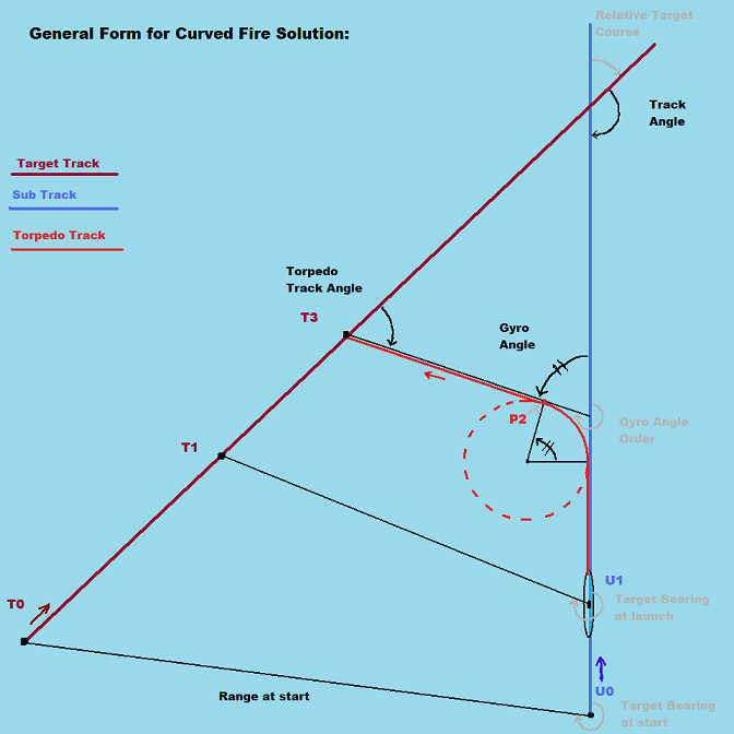


Also, it is important to remember that the solution math/geometry is based on the relative positions at T0 and U0, the last observation before calculations are started. While later observations can be made to confirm data, or monitor the situation, the results of the calculations use this as the reference point. The time to position, target/sub advance and such are calculated from this point.


Comprehensive Example:


Step 1:


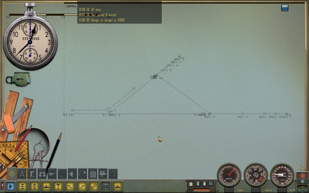
Target data is obtained by observation and plotting. Note the +141 deg. track angle


Step 2:


Calculate firing solution.
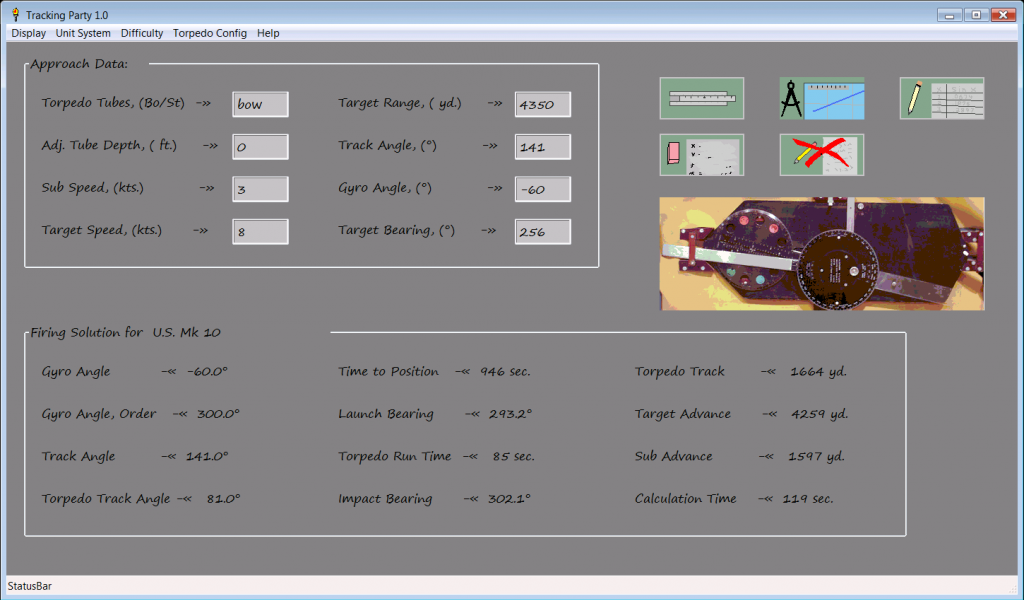


You will probably write down the most important information here. Note that the time to position is 946 sec., thats almost 16 minutes. I don't usually advise computing a final solution this far in advance, but one can compute a preliminary solution, and if it appears satisfactory, and nothing changes to disrupt you plans, you can go with it. You should always allow at least a couple minutes to set gyros, open torpedo tube doors, and perform any other last minute tasks.


Of course, it doesn't hurt to look over the sketch to verify the solution is correct, and conforms to the approach plan. If you made any mistakes in entering the approach data, you should be able to spot it here. It also makes a handy record of the attack.


Step 3:
Compute gyro setting bearing.


Since it isn't possible to set the torpedo gyro angles directly, we must compute the bearing needed for obtaining the desired angle. This step is not neccessary if we want to make a 0 deg. gyro shot.
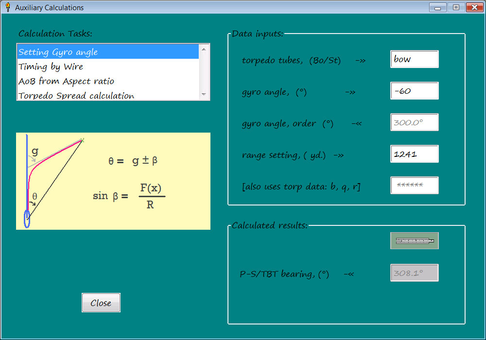
Now we know we must turn the periscope or TBT to 308.1 deg. to set the gyro angles.


Step 4:
Set torpedo gyros


With the correct range, speed set to 0, and the periscope pointed to the calculated bearing, the red button is pushed, and you're set. After this, the slideout panels can be put back out of the way. Notice the P/S head is below the surface of the water. It is not required to do this with the target in sight, or wait until the last minute.


Step 5:
Launch torpedoes as target reaches bearing.


The torpedoes are launched at desired points (from bow going toward stern) as the target passes the P/S reticle. A longitudinal spread is obtained this way. If it was desired to use a divergent angle spread, the auxiliary window would be used to calculate a spread for a given time interval, say 6 or 8 seconds. In this case, the first torpedo would be aimed near the stern (or even behind it), and the following shots advanced in the direction of the ship's travel. With this technique, only the first torpedo need be aimed visually, the remainder being launched at the prescribed interval and offset angle to obtain the spread.
 
For example, with the above set-up, and a 350 ft. long target, 25% coverage, and an 8 sec. launch interval, the calculator returns a 3.0 degree angle. So, the 1st torp would be launched at the stern, the 2nd 8 seconds later with a 3.0 deg. offset, and the 3rd 16 sec. after the 1st, with a 6 deg. offset., etc., etc. The 25% coverage is, of course, per torpedo. Three torpedoes would give you 75% coverage total.


Step 6:
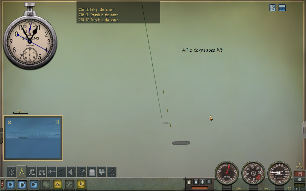
Observe results.


Here, all three torpedoes hit the target. If no course or speed changes have been made (by either sub or target), the torpedoes will hit at the calculated impact bearing.


High Realism Mode:
If you have mastered the basic technique, and wish to have a more realistic (and challanging) game, there is the High Realism Mode. In the HR mode the program computes a "calculation time" and checks for possible errors. After all, human crewmen make mistakes, and cannot complete complicated calculations in a snap.

To implement the HR mode, pull down the Realism Configuration panel by clicking on the "Difficulty" part of the menu at the top of the main window. Select the High Realism Mode of the radio buttons.
Then chose whether you want an actual delay or not. If you check the actual delay box, the calculation results will actually be delayed for a few minutes, otherwise you can implement the delay in a manor of your own choosing. This is to provide compatability for different styles of play. Some like to play with very few, if any, pauses in the game, some will often pause the game. You can use whichever option works best for you.

Finally, chose an appropriate skill level for your "tracking party". You can use any number you like (including fractional levels), but I suggest staying in the range of 1 to 5, for realistic play. Use the following as a guideline:

skill level_____________ description

1.0 .................marginal, frequently makes mistakes, substandard
2.0 ................ fair ability, but makes mistakes sometimes
3.0 .................above average ability
4.0 .................good ability, makes few mistakes
5.0 + ..............superior ability, seldom makes mistakes


I would suggest an inexperienced (but competent) crew would rate 2.0 +/- .5 on the first patrol, and if you use the technique successfully, raise it by a full point for the second patrol. For a third patrol, an increase by .5 to 1.0, and after a level of 4.0 it should not increase by more than .5 each patrol.

If the random check indicates a mistake, one of about ten quantities used in the calculations is picked randomly, and one of the digits to the left of the decimal point is changed by 1. This could result in a very large error (242 degrees changed to 342), or a small error (7350 yds. changed to 7340, a rounding error almost), or something in between. Sometimes it is possible to see the error by looking over the numbers or sketch, sometimes not. It is entirely possible for your crew to make an error, and the attack to go through and get hits anyway, and you be none the wiser. If a mistake is suspected in High Realism Mode, checking the same problem later (in Training Mode), will reveal if any mistakes were made.

Note that the solution results are displayed differently in HR mode. Angles are rounded to the nearest 1/4 degree, and distances to nearest 50.

The skill level also affects the computation time, but the change is not linear. The time it takes will never go below 1 minute no matter how high the skill level. Generally, you should try to plan your approaches so you have at least 3 minutes between obtaining the data from your last observation, and launch. It will usually take about 2 or so for the calculations, and you might need to do some other last minute tasks or checks, before launching. Note that you do not need to complete the firing solution calculation before setting the torpedo gyros or using the Setting Gyro angle task. However, the Torpedo Spread task, and the Sketch functions require a finished solution for their inputs. The main window calculation will produce a sound (of crumpled paper) when finished, to tell you it's done; the idea here is that you can set the "crew" to working on the solution, and go back to the game, and will hear when their finished.

Using this technique with the High Realism Mode, forces you to think ahead, just as it did in real life. Note that the difficulties with this sort of technique, being used to attack fast moving and zigging targets, lead to the development of the Torpedo Data Computer.


Happy Hunting!

TorpX is offline   Reply With Quote
Old 10-28-13, 08:57 PM   #60
TorpX
Silent Hunter
 
Join Date: Sep 2010
Posts: 3,975
Downloads: 153
Uploads: 11
Default

I was going to post this before, but it slipped my mind. I've tested this method with the Mk. 10 torpedo with the S-18 class, and the Mk. 14 with the Porpoise class. Most of the testing was done with the S-18, but, as the torpedo turning radius and reach seem to be the same, I didn't have to start from scratch. I may calculate the relevent figures for other torpedo combinations down the road.


Mk. 10 torpedo and S-18 (default):

tube distance_______85 ft.
torpedo reach______343 ft.
turning radius______310 ft.
luanch lag_________ 2.8 sec.


Mk. 14 torpedo and Porpoise:


tube distance_______112 ft. (bow)______136 ft. (stern)
torpedo reach_______343 ft.
turning radius_______310 ft.
luanch lag__________ 4.0 sec.


Arriving at these figures involved a great deal of time consuming, tedius work. It wasn't hard to obtain approximate values, but I wanted to get the most accurate figures possible.

Unfortunately, the different methods I was using didn't seem to agree. After much fruitless effort, I decided to toss out the provisional values I was using and start over. This time, I first took the trouble to tabulate the actual bearing angle that the periscope is pointed to. This was necessary because the angle indicated on the index ring is not the true angle. The number of pixels between the degree marks is not the same. On most of the dial, there are 3 pixels between marks, but on some there are only 2. Anyway, I tabulated the number of pixels from 0 to 360 so I could make my computations on the basis of the true angle. [I assume that the number of pixels and the accuracy of the index bearing ring will depend on the mods you have and your display resolution. I was using RFB here as I wanted to make use of the individual degree marks, and the stock game only has marks every 5 degrees.] After all this, the different methods used to estimate the torp performance values agreed pretty well.

My intuitive estimate of the error is that the torp turning radius is probably within 5 or 6 ft. of the true value, and the torp reach is within about 10 or 15 ft. If someone happens to know what values the game uses; please don't hesitate to speak up.

TorpX is offline   Reply With Quote
Reply

Tags
algebra, fire control, firing solutions


Posting Rules
You may not post new threads
You may not post replies
You may not post attachments
You may not edit your posts

BB code is On
Smilies are On
[IMG] code is On
HTML code is Off

Forum Jump


All times are GMT -5. The time now is 12:00 AM.


Powered by vBulletin® Version 3.8.11
Copyright ©2000 - 2024, Jelsoft Enterprises Ltd.
Copyright © 1995- 2024 Subsim®
"Subsim" is a registered trademark, all rights reserved.