
|
|
SUBSIM: The Web's #1 resource for all submarine & naval simulations since 1997
|
SUBSIM: The Web's #1 resource for all submarine & naval simulations since 1997 |
|
|
 10-30-07, 10:07 AM
|
#1 |
|
Rear Admiral
 Join Date: Apr 2006
Location: Swindon, England
Posts: 10,151
Downloads: 35
Uploads: 0
|
Sweet
Very detailed posts I wonder what uboat Revell based the model on :hmm: Obviously not a B und V boat |

|

|
|
10-30-07, 05:44 PM
|
#2 |
|
Grey Wolf
 Join Date: Sep 2007
Location: Mitcham/London
Posts: 818
Downloads: 0
Uploads: 0
|
First test of the rivets.
 It is only the test , and on the sub the rivets are much tighter. I think it looks satisfactory. 
|
|
|
|
|
11-01-07, 04:26 AM
|
#3 |
|
Grey Wolf
Join Date: Sep 2007
Location: Mitcham/London
Posts: 818
Downloads: 0
Uploads: 0
|
Im having trouble finding good , clear pictures of the subs saddle tanks. Revell kit is simplyfied in this area and the surfaces are to straight , while the real boats had some dents and tin ripple to the tanks. Problem is i can not locate reference picture regarding internal ribing of the tanks. If someone has picture or drawing of that part of U-boat it will be highly apreciated.
Another aspect is the vents that are located on upper surface of the saddle tanks. Again , the pictures i have are not conclusive , and most of the fotos are of the boats submerged wchich is of no help. Thanks in advance. TBC... |
|
|
|
|
11-01-07, 10:35 AM
|
#4 |
|
Sea Lord
 Join Date: May 2005
Location: Under a thermal layer in chilly Olde England
Posts: 1,842
Downloads: 0
Uploads: 0
|
I've included some pictures below, but...
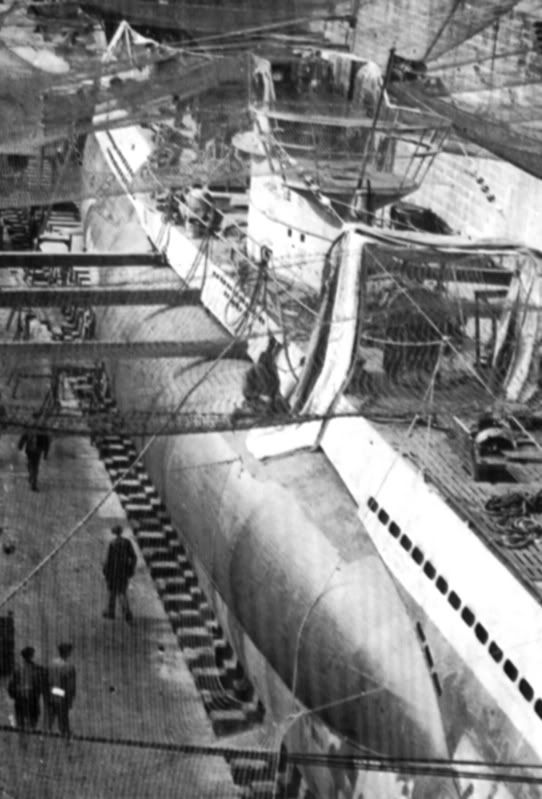
It will help you to understand what it goes like if you know a little bit about how they built the Type VII. It was built out of circular steel sections which were welded together, the middle two were purely cylindrical, but those which tapered to the bow and stern were basically conical. All of these were solid tubes which then had holes pierced in them where necessary, such as for the torpedo tubes, hatches and access to the conning tower, this formed the pressure hull. When the pressure hull was in one piece, the hole for the conning tower would be cut and thus things could be lowered inside to build the interior. While this was going on, the outer hull could be added. The outer hull was basically streamlined plating added fore and aft, with a deck along the top, supported by steel ribs which were welded to the pressure hull, the ribs typically being 60 centimetres apart, the outer hull was pierced with the free-flooding holes but where it met the saddle tanks, it was supported on rib stanchions thus leaving a gap between the outer hull plating and the top of the saddle tanks, and you can see these supporting ribs on a picture I have attached. Only on the underside in the centre section was the pressure hull used to form part of the exterior shape (underneath). So what you basically have is a big long cigar shape, with the outer hull sitting on top of it, with a big gap in between along the top so that things like external stowage, retractable bollards the anchor winch motor etc etc have somewhere to go. Sort of a bit like a 'sprung floor'. This gap being the reason for the many lift-up hatches along the deck, to allow access to various bits and pieces, although some of these access hatches were only intended to be used for dockyard servicing. The deck, incidentally, was covered with wooden planking so that it would not ice up so quickly as steel, and because it was simpler to leave a 1 centimetre gap between the planks so that it would assist in dive flooding, than it was to make something of that nature in steel. 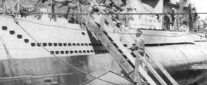 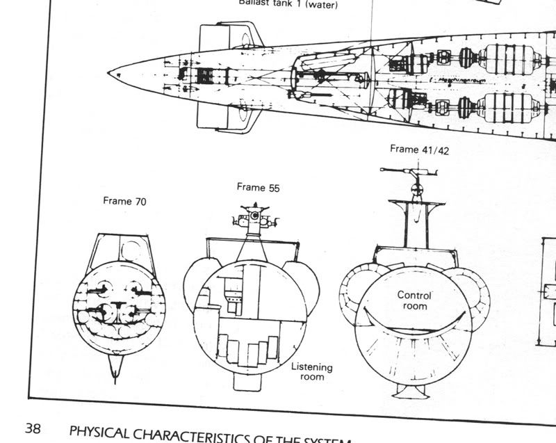 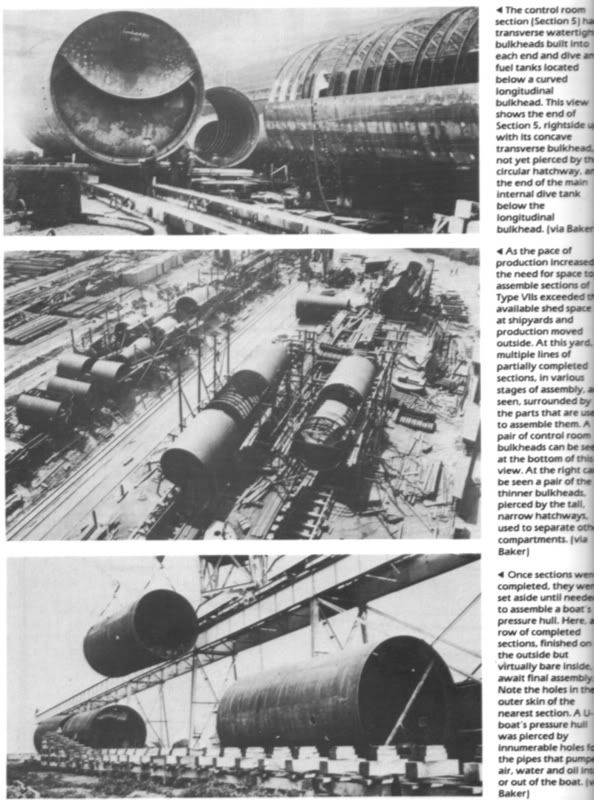 Hope this helps. I've got plenty more reference if you need it, so just shout out if you'd like to see more.  Chock Chock
__________________

|
|
|
|
|
11-01-07, 01:43 PM
|
#5 |
|
Grey Wolf
Join Date: Sep 2007
Location: Mitcham/London
Posts: 818
Downloads: 0
Uploads: 0
|
Thank you for the superb answer Chock. Very important info there , but what im having problem with is the internal ribbing of the tanks. I understand how U-boat was build - regarding structure of the hull. I know there were ribs / cylindrical shaped steel rings , that were covered on outside with sheet of steel. The tanks i understand were added / welded / to the main body of the boat , with some sort of support underneath. These were the ribs of the tank. Problem is i do not know how many ribs were there per tank , and what was the spacing of them looking from the side.
I gather the welds on the tank do not represent the actual spacing , as it looks to far apart. What i was trying to do is to shape the tanks / similar to what i done with the main body of the hull / simulating indents and accidents during u-boats life. For that to achieve i need some reference regarding those ribs. Picture below shows model of Wink Grisé where you can see the shadow of the ribs.  Hope you can help Chock. TBC... |
|
|
|
|
11-01-07, 01:55 PM
|
#6 |
|
Sea Lord
Join Date: May 2005
Location: Under a thermal layer in chilly Olde England
Posts: 1,842
Downloads: 0
Uploads: 0
|
Currently scanning some pics, check back in ten mins!
Chock
__________________
|
|
|
|
|
11-01-07, 02:20 PM
|
#7 |
|
Grey Wolf
Join Date: Sep 2007
Location: Mitcham/London
Posts: 818
Downloads: 0
Uploads: 0
|
RGR

|
|
|
|
|
11-01-07, 02:26 PM
|
#8 |
|
Sea Lord
Join Date: May 2005
Location: Under a thermal layer in chilly Olde England
Posts: 1,842
Downloads: 0
Uploads: 0
|
Okay, the pictures are of Otto Kretschmer's U-99 (VIIB) at drydock in Lorient in late 1940, so you'll need to use them as a guide rather than gospel for a VIIC, the main external visual difference between the VIIB and C being altered positioning of the external ventillation ducting, so it should serve as a good guide, technically, the tanks were different on the two, with an additional small buoyancy tank added to the main tank array, but externally things looked no different on the tanks. The schematics were tricky to scan, as they were on a tightly folded page, although you can determine many rib positions from them all the same. There is good reference for rippling detail on the last picture, which I can get to you at a higher resolution if you need it.
 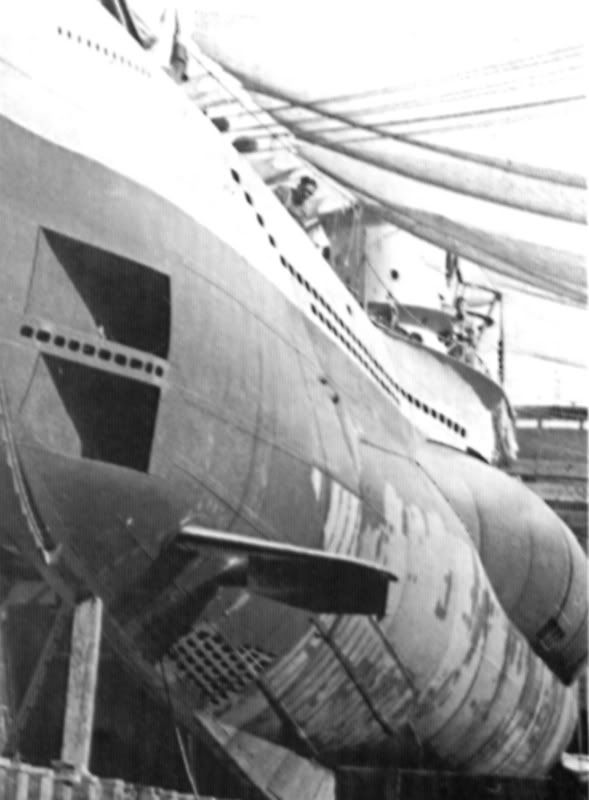 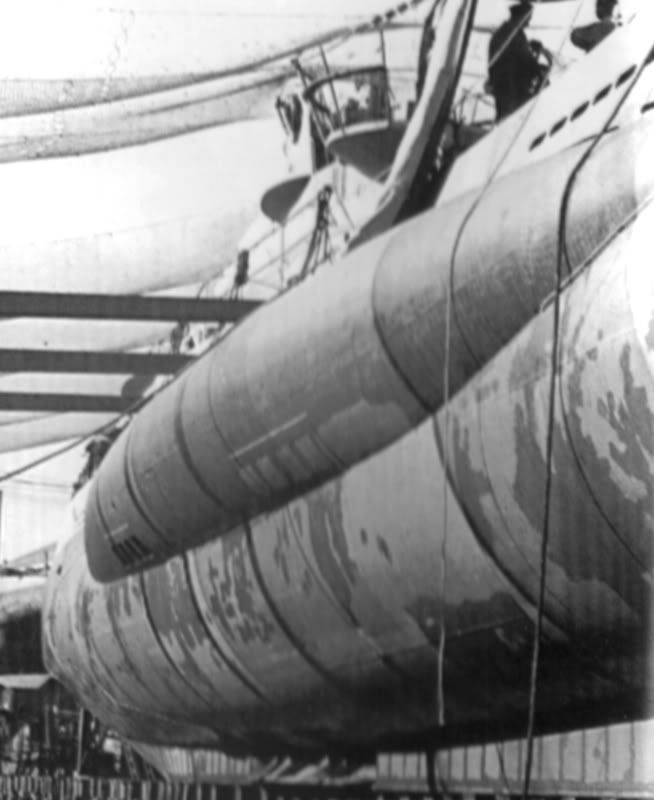 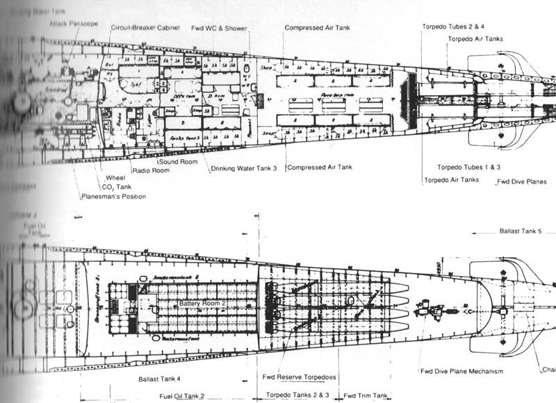 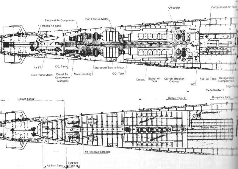 Try not to get glue on the carpet:rotfl: Chock
__________________
|
|
|
|
|
05-19-12, 04:00 PM
|
#9 |
|
Swabbie
 Join Date: May 2012
Posts: 12
Downloads: 188
Uploads: 0
|
Hiiiii
I remember this model, it was wonderful, when I was a child, for my birthday my parents buy me the U-Boot VII - C , the model of Gunter Prien, it was opended and you can see all the machines, the torpedo camera. Was perfect. Now I have other models, but I'm not make it, not free time for it, maybe into a few years. It's a plastic models and it is eternal. 
|
|
|
|
|
11-10-12, 02:37 PM
|
#10 |
|
Swabbie
Join Date: Mar 2007
Location: Gibsons, BC, Canada
Posts: 8
Downloads: 42
Uploads: 0
|
I, like many others came across this amazing project quite late. The talent, eye for detail and incredible tenacity of the builder are simply epic. Unfortunately, for reasons known only to the photo depository site, the pics of the last year or so have been deemed forbidden due to some supposed indiscretion.
That aside, has anyone seen or heard anything from Siara since his last post, over a year ago now? He mentioned he was moving back to Poland and was going to be selling off his larger collection items. I think we can all agree to hope that there is nothing amiss in his life that has caused him to move, dispose of his passion and virtually disappear so suddenly. James
__________________
Asus P5Q Intel Core2Quad Q6600 (2.4) 4gig DDR3 PC3 1066 Sapphire Radeon 4870 512mb |
|
|
|
|
11-22-12, 05:08 PM
|
#11 |
|
Ensign
 Join Date: Jan 2012
Location: NY Harbour, Periscope depth.
Posts: 235
Downloads: 160
Uploads: 0
|
Dude I build websites for a living, and would gladly put all these pics into a gallery website if ever you fancied it. This is pure awesome. I'd even host it
|
|
|
|
|
11-22-12, 05:17 PM
|
#12 |
|
Eternal Patrol

 Join Date: Nov 2002
Location: High in the mountains of Utah
Posts: 50,369
Downloads: 745
Uploads: 249


|
Unfortunately he hasn't even visited Subsim in more than two years. I would love to see the finished product, but it's looking less and less likely.
__________________
Never do anything you can't take back. Rocky Russo |
|
|
|
|
11-24-12, 05:52 AM
|
#13 |
|
Watch
 Join Date: Mar 2010
Posts: 18
Downloads: 42
Uploads: 0
|
I think i found his old blog, not sure if i missed it earlier.
http://u-552.blogspot.ca/ It ended before he was finished there too. I think it has his email at the bottom if anyone else wants to try to contact him. |
|
|
|
 |
| Tags |
| model, scale models |
|
|


 Hybrid Mode
