Silent Hunter 
Join Date: Sep 2010
Posts: 3,975
Downloads: 153
Uploads: 11
|
Tracking Party 1.1 is Released!
No replies yet. I'll just assume this means people are frozen in anticipation, lol.
Tracking Party 1.1 is released, and available in the downloads section under Utilities:
http://www.subsim.com/radioroom/down...o=file&id=4236
Here I'll provide a tutorial fully explaining the use of the program/method.
Installation:
When you unzip the file, you should have a folder with:
Tracking Party 1.1.exe
Tracking Party 1.1.tkn
3x .SLL files
5x .DLL files
2x .wav files
1x .ico icon
1x Save folder (empty)
1x images folder (17 .bmp files)
this help file
Simply move the folder, with the inside files/folders as-is, to the location of your choosing. I put mine in a folder named SH Auxiliary, but it doesn't really matter, as long as you know where it is, and can reach it. Then make shortcuts from the Tracking Party 1.1.exe, and this help file, and put those on your desktop, or wherever you want them. That's it, you're done! The first time you run Tracking Party, it will create a config. file that stores the display, unit system, and realism settings, and a torp cofig. file that stores the torpedo performance numbers. These can be edited from the menu dialog panels when the program is running.
Configuration:
There are 5 items at the top of the main window that can be accessed to change the various elements of the program.
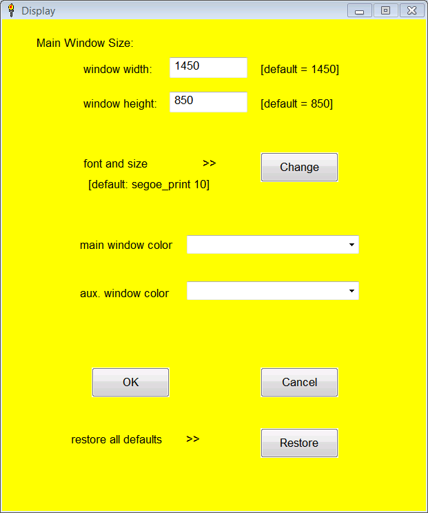
Display - calls up a display config panel where you can change the main window size and color scheme. The auxiliary window's color can also be selected; the size will be proportional to the main window size. Also, a different font and size for type can be chosen. (This is necessary if, say, you want to have a smaller window.) The default font is Segoe_print 11, but this font is not very readable at the smaller sizes, so you might want to use something else if you want a small window. Don't be afraid to play around with the display; you can always easily restore the default configuration, if the display gets messed up. The colors of the main and auxiliary windows can also be changed.
Unit System - changes displayed units of length from english to metric. Defaults to english.
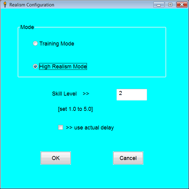
Difficulty - allows selection of either "Training Mode" or "High Realism Mode". There is a selectable crew skill level, delay factor. These are only relevent in the High Realism Mode. The program defaults to Training Mode. The details of the High Realism Mode are explaned below. Defaults to Training Mode.
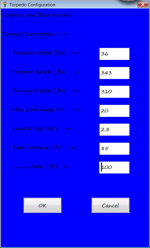
Torpedo Configuration - allows torpedo performance parameters to be edited. These include speed, reach, turning radius, bow and stern tube distance, maximum dive angle, and launch lag. The max. dive angle only comes into play if torpedoes are launched from deep submergence. The stern tube distance for the default S-18/Mk. 10 torpedo combination is an untested guess, as the SH4 version of the S - class has no stern tube.
About - self explanitory.
The program stores any changes made to a file, so it remembers your selections and there is no need to configure it each time you start it up. If the files are deleted, or corrupted, the program recreates them.
Main Window:
Here is the core of the program where the torpedo firing solution is calculated and displayed. The 8 textboxes in the top half of the window are where the firing data is entered into the program. The bottom half is where the computed firing solution is displayed. The 5 buttons at the top right control the flow of the program.
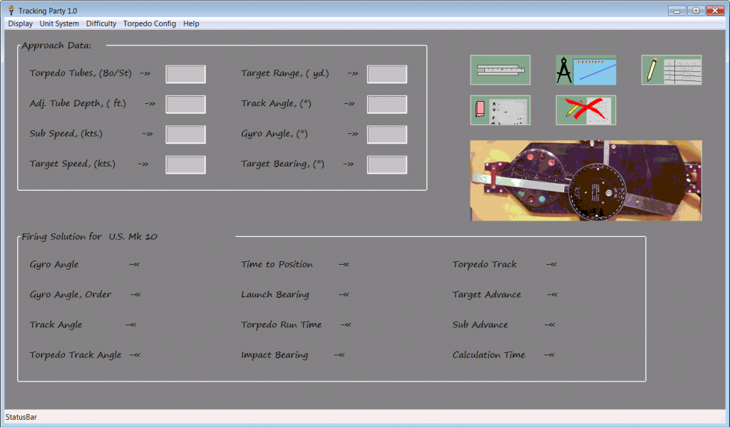
Data boxes:
1. torpedo tubes - bow or stern. If nothing is entered will default to bow.
2. adjusted tube depth - the distance the torpedo must climb to reach set depth. Defaults to 0. Not normally important.
3. sub speed - self explanitory.
4. target speed - self explanitory.
5. target range - self explanitory.
6. track angle - the angle formed from the target's path ahead, to where the sub's path intersects. Can be either negative (port) or positive (starboard).
7. gyro angle - the angle set on the torpedoes; i.e. how much the torpedoes turn. Can be either negative (left) or positive (right).
8. target bearing - self explanitory.
Solution spaces:
1. gyro angle - restatement of gyro angle entered.
2. gyro angle, order - gyro angle indexed from 0 to 360 degrees.
3. track angle - restatement of track angle entered.
4. torpedo track angle - the angle formed by the target's track ahead measured to the torpedo track. Can be either negative (port) or positive (starboard).
5. time to position - the time in seconds for the sub and target to reach the computed firing position.
6. launch bearing - the relative bearing the target should reach for torpedo launch. This is the most critical element of the solution.
7. torpedo run time - the time required for the torpedo to reach the target from launch to impact.
8. impact bearing - the relative bearing the target will reach when torpedoes impact, assuming the sub does not change course.
9. torpedo track - the length the torpedo actually must travel.
10. target advance - the distance the target travels from the plotted refrence point to launch. Displayed mainly to aid plotting.
11. sub advance - the distance the sub travels from the plotted refrence point to launch. Displayed mainly to aid plotting.
12. calculation time - the time required for the "crew" to compute firing solution.
Only relevent in High Realism Mode.
Buttons:
Slide rule (upper left of group) - calculates firing solution.
Eraser (lower left of group) - clears data and results.
Devider/Chart (upper middle of group) - opens up window where sketch of firing is made. Allows user to edit and save sketch of attack approach.
Red cross (lower middle of group) - shuts down program and all windows.
Pencil and worksheet (upper right of group) - opens up window for auxiliary calculations.
Large button - flips image from Mk. VIII Angle Solver (in box) to functional diagram. Has no effect on program execution.
Auxiliary Window:
The auxiliary window allows different calculations to be made in one window. On the right there are 5 textboxes for the input of data, 1 or 2 boxes for output and a single button for run the calculations.
The left side has a list box with the different types of calculation options. Below this is a large button that has a diagram which changes when different calculation options are selected. The small button at the bottom left closes the window.
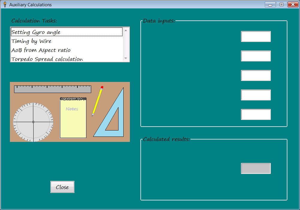
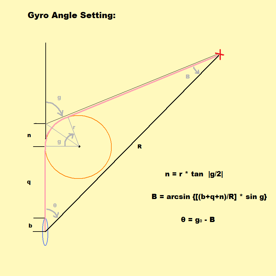
Setting Gyro angle - This is the most important aux. function. It allows you to set the torpedo gyros to an arbitrary value. The tubes used (bow or stern) are input in the first box, the gyro angle desired in the second. The third box isn't used for input, but only displays the gyro angle, order (not really required). The fourth box is the range setting. This is not the range to target, but the range on the TDC dial when the bearing is transmitted to the TDC. The fifth box is a place holder to remind the user that the calculation also uses the torpedo parameters stored in the Torp config. file. If there was some way to set the torpedo gyro angle directly, this function would not be needed, but alas, there doesn't seem to be one in SH4. In stock SH4 the longest range one can input into the TDC without a target selected is 1,241 yds. It is porbably best to use the longest range possible. If you desire to make a zero angle gyro shot, this process is unneccessary.
For example: if you desire to use a -40 degree gyro angle with a Mk. 10 torpedo (S- class) and input a range of 1241 yd. , the program returns a bearing of 325.4 degrees. So after putting 1,241 yds. on the TDC dial, (target speed should be zero), turn the periscope/TBT to 325.4 deg. and hit the red button. This forces the unit to change the gyro angle to -40 deg.
Timing by Wire - This allows you to estimate the target's speed by measuring the time it takes to cross the periscope reticle. Target length, time, sub speed, bearing, and Aob are input. Note that Aob can be either positive (starboard) or negative (port).
Example: a 375 ft. ship takes 22 sec. to cross the wire. It has a -75 deg. Aob at bearing 55 deg. and the sub is moving at 2.5 kts. The target is estimated to be traveling at 12.2 knots.
Aob from Aspect Ratio - The program uses actual target length, height, and observed length and height. The observed length and height can be the reticle marks on the periscope/TBT or any arbitrary unit as long as they are the same value (degrees or milliradians, for example). The program uses a mathematical model that takes into account target width making Aob estimates near 0 or 180 degrees more accurate.
Example: A target of 375 ft. length and 95 ft. height, has an observed length of 8.0 milliradians and an observed height of 3.5 milliradians. An Aob estimate of +/- 35 or +/- 145 degrees is returned. (One cannot determine which is correct by aspect ratio alone; by seeing which end is the bow and observing the direction of travel, the correct value can be selected.)
Torpedo Spread calculation - The program uses target length, spread fraction (expressed as a percentage) and the launch interval to calculate a divergent angular spread. As the program requires solution data, the calculation must be done after a firing solution is computed. The number returned is the angular spread (positive or negative) to be used between each torpedo. This is more fully explained in a comprehensive example later.
Optimum Track angle - Uses target speed and torpedo speed to calculate optimum track angle as defined by USN. This is more for player information than any specific requirement.
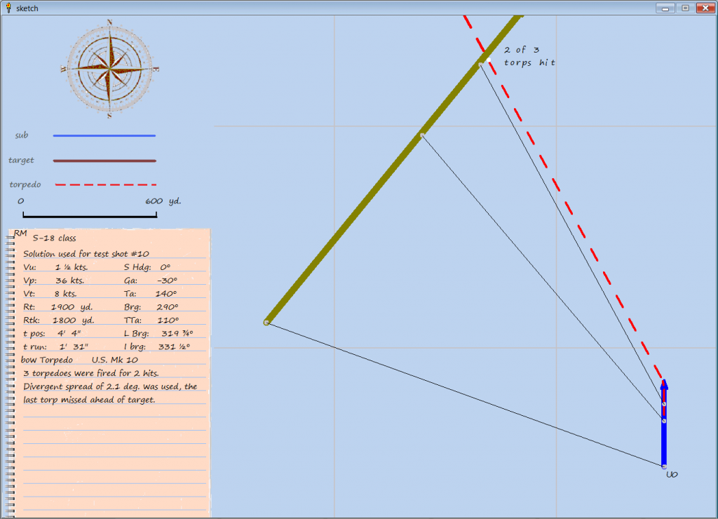
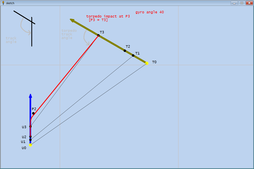
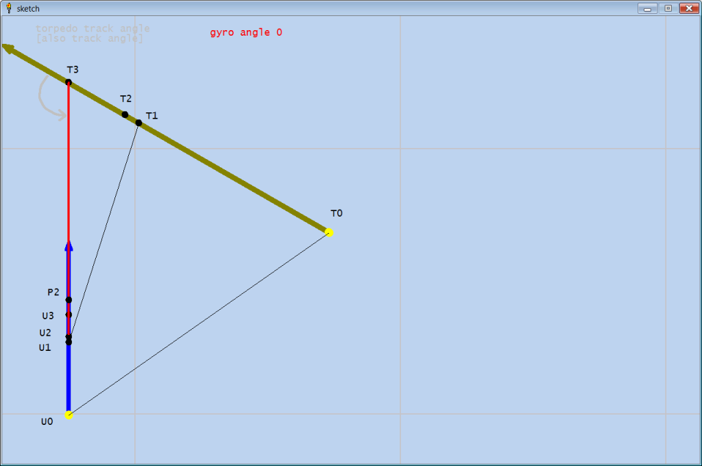
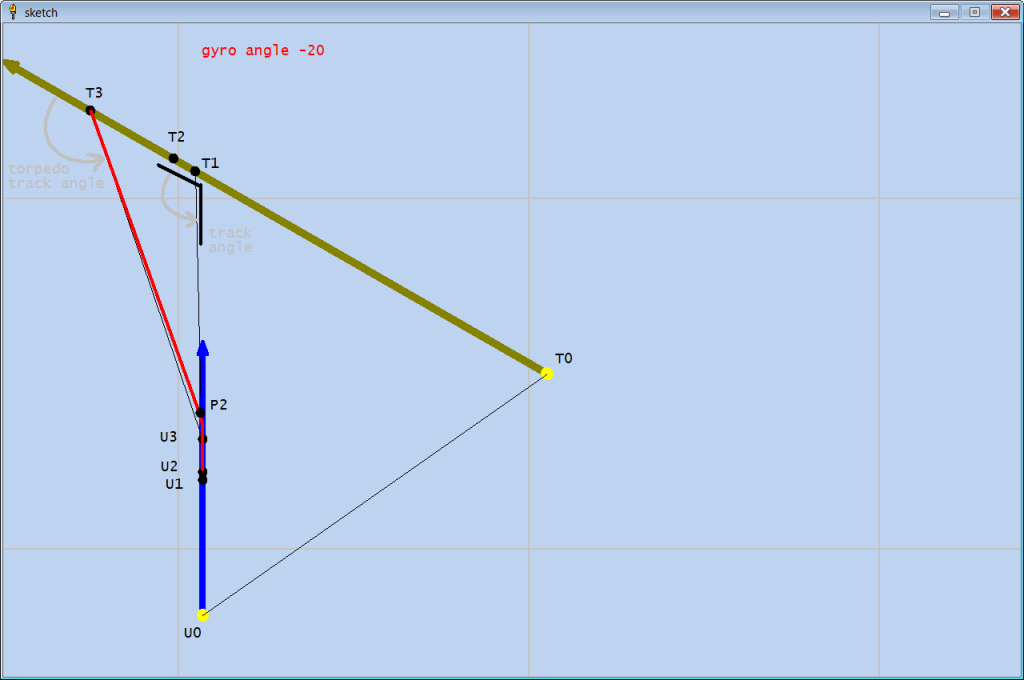
Sketch Function:
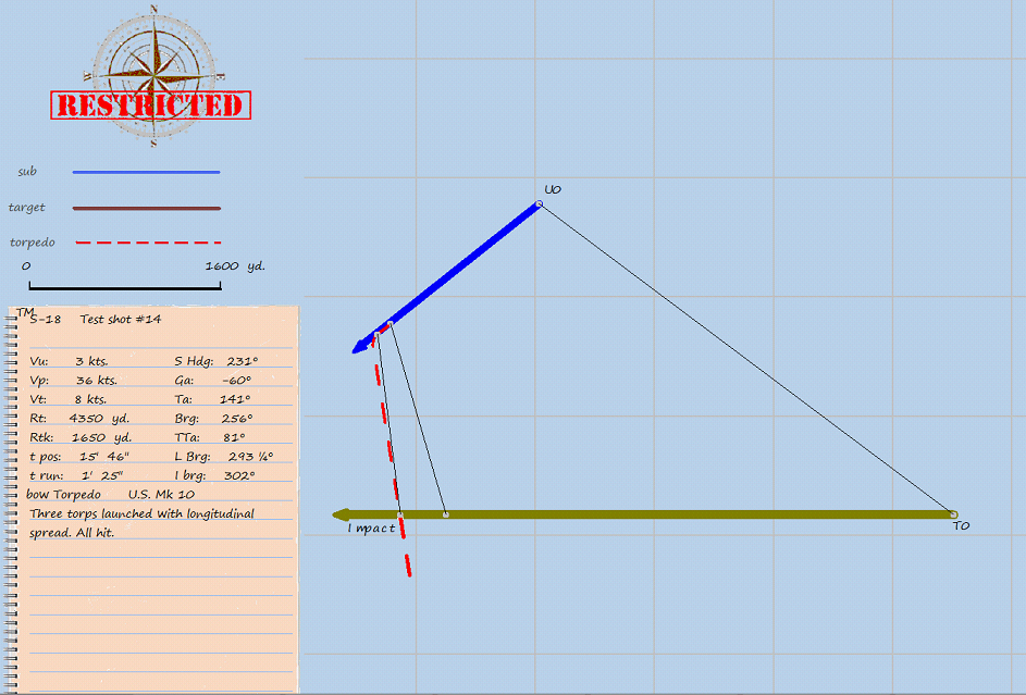
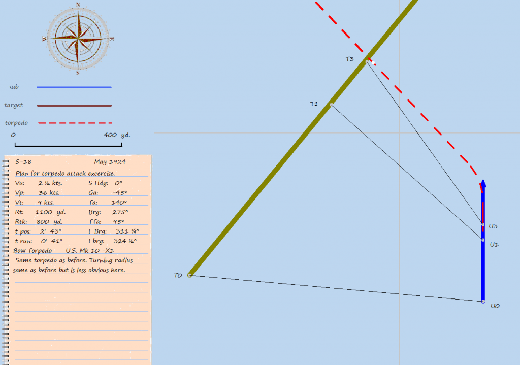
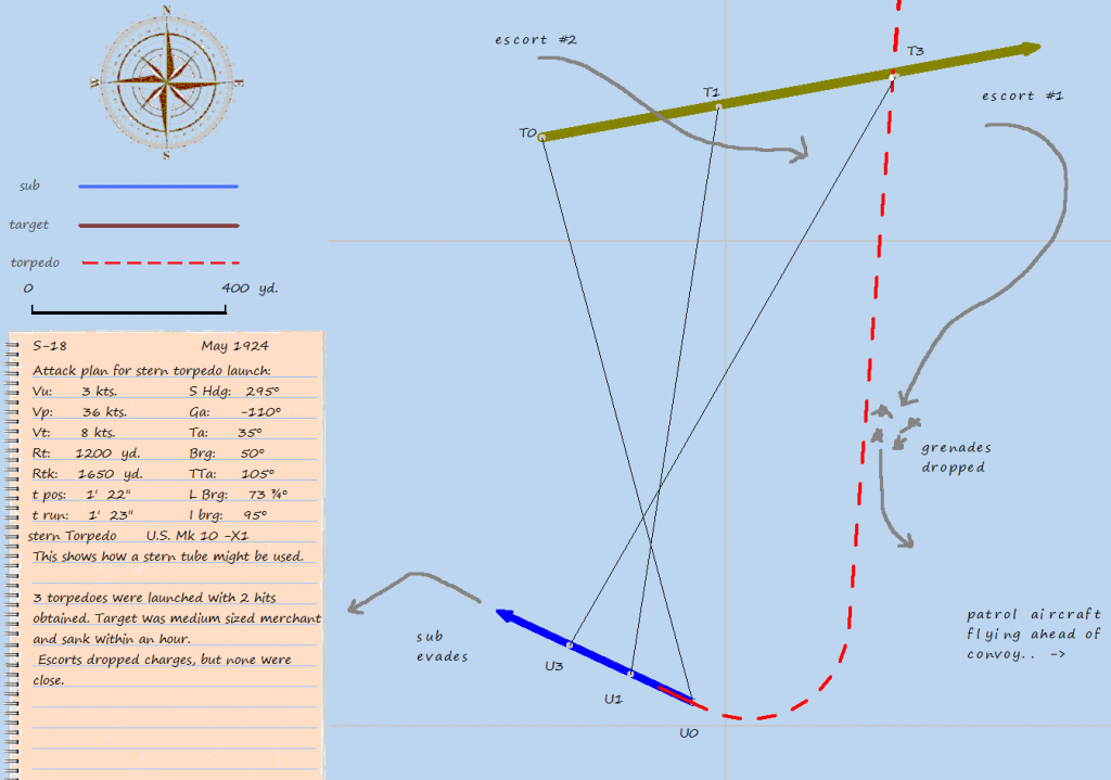
After you enter all the appropriate firing data, and calculate a firing solution, you may want to sketch out the approach and solution to see what it looks like, and verify that the angles and data are what you intended. This is easily done just by hitting the sketch button. The program will automatically draw out the target track, the sub track, and the torpedo track from the input reference point. The signal points, T0, T1, T3, U0, U1, U3, and P3 are indicated, as are the bearing lines between them. Additionally, the firing data and solution are written on a "notepad", and comments or changes can be made by the user. The whole drawing, with any writing or drawing made by the user, can be saved into a file for a permanent record. The window has a legend and scale in yards (or meters). Grid lines are in 1,000 yds. or m.
Here are the controls used in the sketch window:
Ctrl + R Redraws sketch so orientation can be changed. Default sketch will always have sub heading north.
Ctrl + T Text boxes activated. Allows user to write in space provided in notepad. After typing out whatever one wants to write Ctrl W
must be used to finish task.
Ctrl + W Writes what user input into text boxes. Must put cursor outside text box to shift focus back to window first.
Ctrl + Z Undo for drawing items in window.
Ctrl + S Saves drawing to bitmap file.
Mouse left button Draws line on sketch.
Mouse right click Allows typing characters at location of cursor. Good for labeling of drawn items for clarity.
Note that the limitations of the programing language make for less than ideal spacing of characters when written on drawing. It is best to write out comments and such in the text boxes where the font is properly spaced.
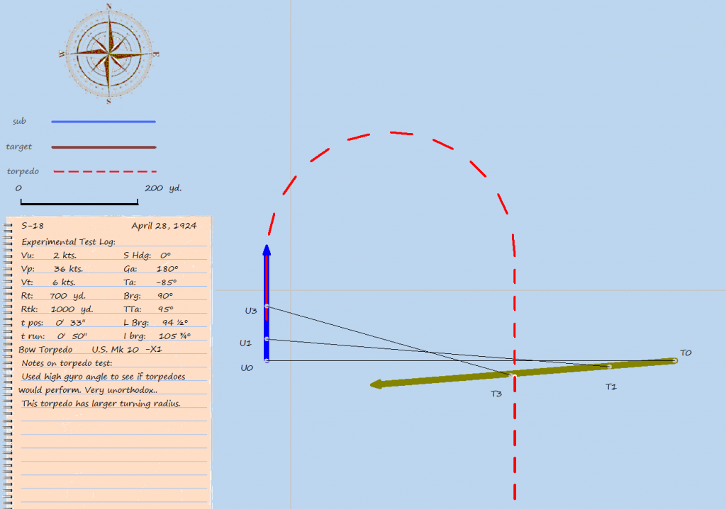
Sometimes the points where the torpedo impacts and where the target ship are supposed to meet, do not match up exactly. There is no need to be concerned about this. It is merely a limitation in the way the language measures and draws angles. I had to compromise between getting the display in the style I wanted, and drawing precision. It is important to understand that the solution numbers are used to make the drawing, not the other way around. In other words, the numerical solution is much more precise than the drawing.
When you save a sketch, it will be in the Save folder of your installation (in bitmap form). You can, of course alter it later and/or convert it to another file format. I added a "RESTRICTED" stamp and sound effect, so you know the file has been saved.
General Issues:
Probably the most likely area for confusion in entering data would be the gyro angle or track angle. The mathematics behind this method can compute a solution for any gyro angle, but the torpedoes themselves were limited to +/- 90 degrees in the case of the Mk. 10, and +/- 135 for the Mk. 14. It is important to remember that you need to enter the values as negative for left turning torpedoes, and positive for right turning torpedoes. Similerly, the track angle must be entered as negative for port angles, and positive for starboard angles. Looking over the solution in the sketch window will usually catch these mistakes.

Also, it is important to remember that the solution math/geometry is based on the relative positions at T0 and U0, the last observation before calculations are started. While later observations can be made to confirm data, or monitor the situation, the results of the calculations use this as the reference point. The time to position, target/sub advance and such are calculated from this point.
Comprehensive Example:
Step 1:
Target data is obtained by observation and plotting. Note the +141 deg. track angle
Step 2:
Calculate firing solution.
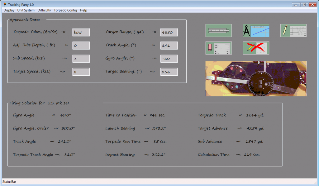
You will probably write down the most important information here. Note that the time to position is 946 sec., thats almost 16 minutes. I don't usually advise computing a final solution this far in advance, but one can compute a preliminary solution, and if it appears satisfactory, and nothing changes to disrupt you plans, you can go with it. You should always allow at least a couple minutes to set gyros, open torpedo tube doors, and perform any other last minute tasks.
Of course, it doesn't hurt to look over the sketch to verify the solution is correct, and conforms to the approach plan. If you made any mistakes in entering the approach data, you should be able to spot it here. It also makes a handy record of the attack.
Step 3:
Compute gyro setting bearing.
Since it isn't possible to set the torpedo gyro angles directly, we must compute the bearing needed for obtaining the desired angle. This step is not neccessary if we want to make a 0 deg. gyro shot.
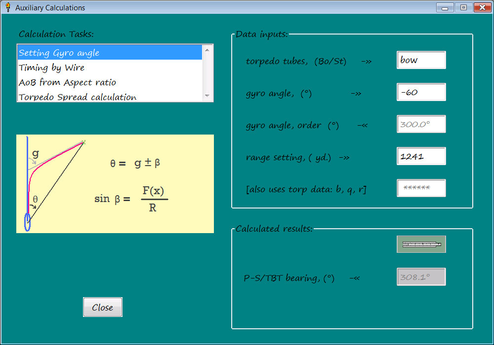 Now we know we must turn the periscope or TBT to 308.1 deg. to set the gyro angles.
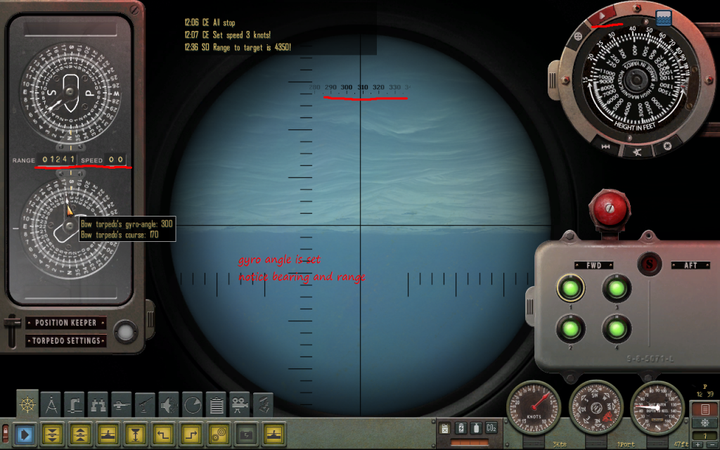
Step 4:
Set torpedo gyros
With the correct range, speed set to 0, and the periscope pointed to the calculated bearing, the red button is pushed, and you're set. After this, the slideout panels can be put back out of the way. Notice the P/S head is below the surface of the water. It is not required to do this with the target in sight, or wait until the last minute.
Step 5:
Launch torpedoes as target reaches bearing.
The torpedoes are launched at desired points (from bow going toward stern) as the target passes the P/S reticle. A longitudinal spread is obtained this way. If it was desired to use a divergent angle spread, the auxiliary window would be used to calculate a spread for a given time interval, say 6 or 8 seconds. In this case, the first torpedo would be aimed near the stern (or even behind it), and the following shots advanced in the direction of the ship's travel. With this technique, only the first torpedo need be aimed visually, the remainder being launched at the prescribed interval and offset angle to obtain the spread.
For example, with the above set-up, and a 350 ft. long target, 25% coverage, and an 8 sec. launch interval, the calculator returns a 3.0 degree angle. So, the 1st torp would be launched at the stern, the 2nd 8 seconds later with a 3.0 deg. offset, and the 3rd 16 sec. after the 1st, with a 6 deg. offset., etc., etc. The 25% coverage is, of course, per torpedo. Three torpedoes would give you 75% coverage total.
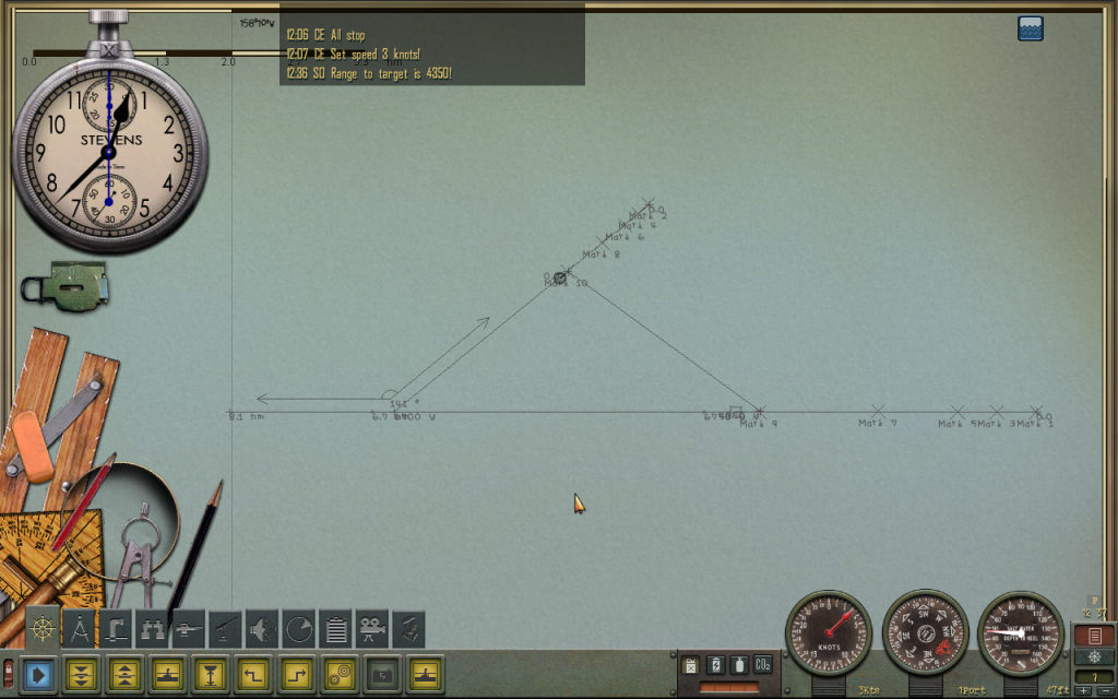
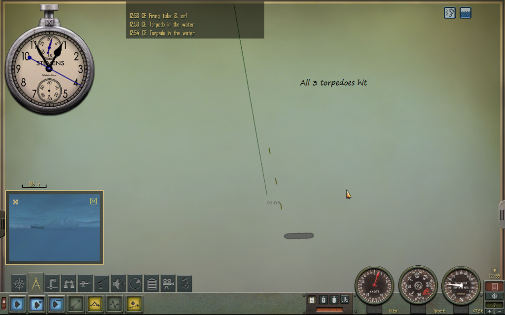
Step 6:
Observe results.
Here, all three torpedoes hit the target. If no course or speed changes have been made (by either sub or target), the torpedoes will hit at the calculated impact bearing.
High Realism Mode: If you have mastered the basic technique, and wish to have a more realistic (and challanging) game, there is the High Realism Mode. In the HR mode the program computes a "calculation time" and checks for possible errors. After all, human crewmen make mistakes, and cannot complete complicated calculations in a snap.
To implement the HR mode, pull down the Realism Configuration panel by clicking on the "Difficulty" part of the menu at the top of the main window. Select the High Realism Mode of the radio buttons.
Then chose whether you want an actual delay or not. If you check the actual delay box, the calculation results will actually be delayed for a few minutes, otherwise you can implement the delay in a manor of your own choosing. This is to provide compatability for different styles of play. Some like to play with very few, if any, pauses in the game, some will often pause the game. You can use whichever option works best for you.
Finally, chose an appropriate skill level for your "tracking party". You can use any number you like (including fractional levels), but I suggest staying in the range of 1 to 5, for realistic play. Use the following as a guideline:
skill level_____________ description
1.0 .................marginal, frequently makes mistakes, substandard
2.0 ................ fair ability, but makes mistakes sometimes
3.0 .................above average ability
4.0 .................good ability, makes few mistakes
5.0 + ..............superior ability, seldom makes mistakes
I would suggest an inexperienced (but competent) crew would rate 2.0 +/- .5 on the first patrol, and if you use the technique successfully, raise it by a full point for the second patrol. For a third patrol, an increase by .5 to 1.0, and after a level of 4.0 it should not increase by more than .5 each patrol.
If the random check indicates a mistake, one of about ten quantities used in the calculations is picked randomly, and one of the digits to the left of the decimal point is changed by 1. This could result in a very large error (242 degrees changed to 342), or a small error (7350 yds. changed to 7340, a rounding error almost), or something in between. Sometimes it is possible to see the error by looking over the numbers or sketch, sometimes not. It is entirely possible for your crew to make an error, and the attack to go through and get hits anyway, and you be none the wiser. If a mistake is suspected in High Realism Mode, checking the same problem later (in Training Mode), will reveal if any mistakes were made.
Note that the solution results are displayed differently in HR mode. Angles are rounded to the nearest 1/4 degree, and distances to nearest 50.
The skill level also affects the computation time, but the change is not linear. The time it takes will never go below 1 minute no matter how high the skill level. Generally, you should try to plan your approaches so you have at least 3 minutes between obtaining the data from your last observation, and launch. It will usually take about 2 or so for the calculations, and you might need to do some other last minute tasks or checks, before launching. Note that you do not need to complete the firing solution calculation before setting the torpedo gyros or using the Setting Gyro angle task. However, the Torpedo Spread task, and the Sketch functions require a finished solution for their inputs. The main window calculation will produce a sound (of crumpled paper) when finished, to tell you it's done; the idea here is that you can set the "crew" to working on the solution, and go back to the game, and will hear when their finished.
Using this technique with the High Realism Mode, forces you to think ahead, just as it did in real life. Note that the difficulties with this sort of technique, being used to attack fast moving and zigging targets, lead to the development of the Torpedo Data Computer.
Happy Hunting! 
|

 05-08-13, 07:26 PM


 Linear Mode

