 10-19-13, 12:47 AM
|
#57
|
Silent Hunter 
Join Date: Sep 2010
Posts: 3,975
Downloads: 153
Uploads: 11
|
Nearly Finished!
Since the new firing solution program is nearly ready for release, I thought I'd show the math for some of the auxiliary functions/tasks.
This is the Gyro Angle Setting calculator. Since there is currently no way to set the torpedo gyro angles directly (at least in the USN side), it is necessary to calculate a bearing, whereby the TDC mechanism, will be forced to set the gyro angle you want. This is the most important of the Auxiliary functions in the program since it will be required for most launches.
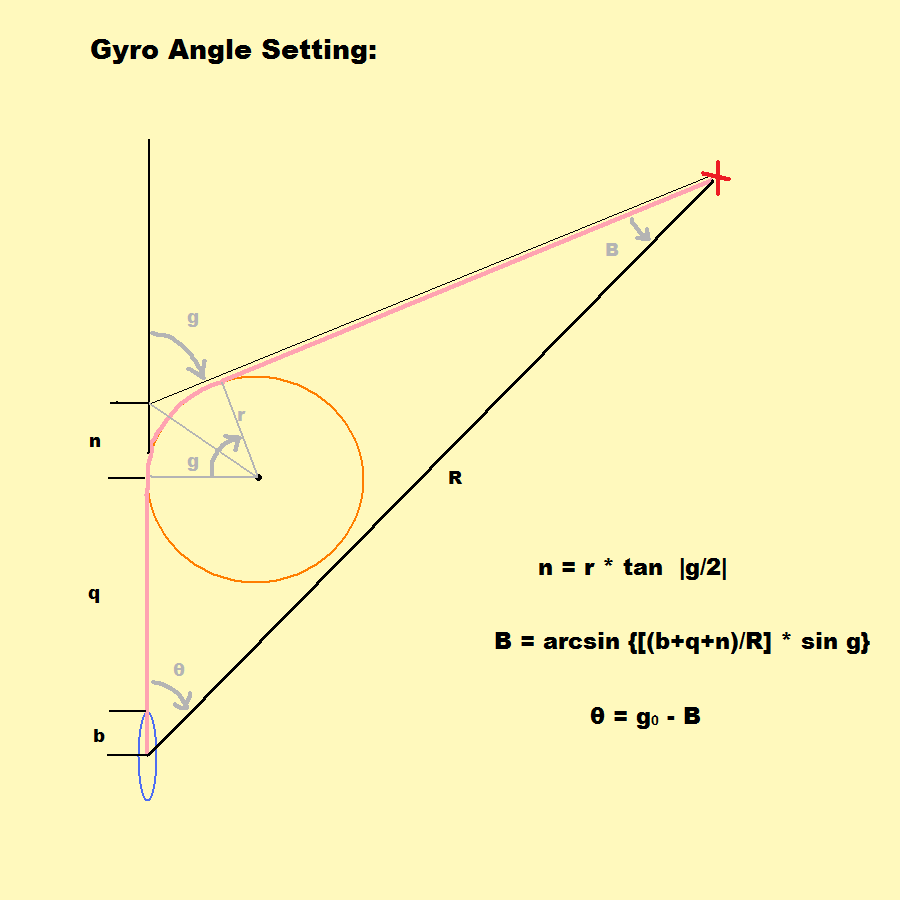
In the above diagram, b is the distance from the periscope/TBT and the end of the torpedo tubes
q is the torpedo's reach, (distance traveled before turning)
r is the turning radius
n is the difference between b+q and the location of where the torpedo track, extended backwards, intersects the sub track
R is the range input
g is the gyro angle
theta is the bearing angle
B is the difference between g and theta
g0, in the last equation, is the gyro angle, order; the gyro angle indexed from 0 to 360 deg.
Note that the red 'X' is not a target ship, but an arbitrary point the the TDC is pointed to, to achieve the desired gyro angle.
Next up is the Torpedo Spread calculator:
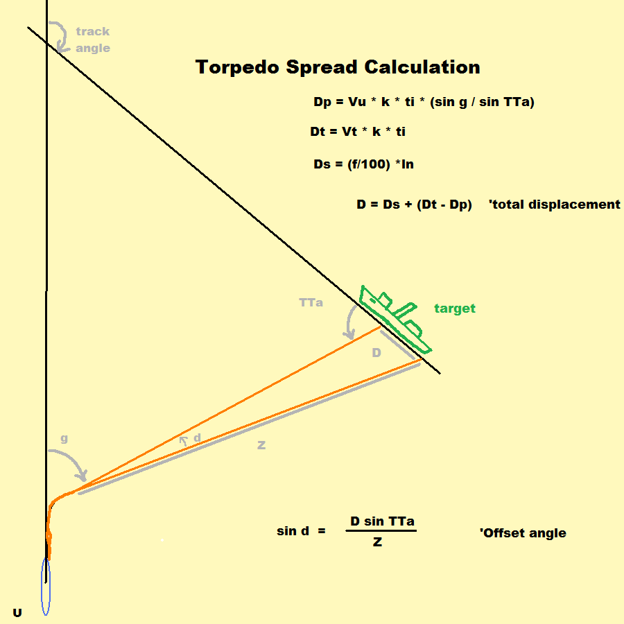
This enables the user to compute a divergent spread after the firing solution has been computed.
The linear displacement is the sum of three things:
- the torpedo track displacement
- target displacement
- spread displacement
The 1st is due to the movement of the sub and the angles of the torpedo track intersecting the target track. In other words, the projection of the torpedo track along the target track, as the sub moves. If the sub was not moving or the gyro angle was zero, this quantity would be zero.
The 2nd is due to the movement of the target. It is the distance the target moves in the interval between the launch of the next torpedo.
The 3rd is simply the displacement along the length of the target. It depends on the length of the target and how much "coverage" is desired.
In the above diagram:Dp is the torpedo track displacement
Dt is the target displacement
Ds is the spread displacement
Vu is sub speed
Vt is target speed
k is constant to convert knots to ft./sec.
ti is time interval
f is fractional coverage, expressed as a percent
ln is target length
D is the total displacement
g is the gyro angle
TTa is the torpedo track angle
Z is the adjusted track range (distance of straight run)
d is offset angle, or spread angle
Using this type of spread in a set-up like that shown above, the first torpedo would be aimed near the stern, and each successive launch would be given a larger offset angle going left.
|

|

|