Silent Hunter 
Join Date: Sep 2010
Posts: 3,975
Downloads: 153
Uploads: 11
|
Algebraic Firing Solution II
AFS II (for curved fire)
Early attempts
Have you ever tried to figure out a way to calculate a firing solution with a non-zero gyro angle? Well, I have. If it's possible to calculate a firing solution for straight fire, why not do the same for curved fire? Years ago, after I had worked out the math for a straight shot, I tried to come up with something ... and got nowhere. A while later, I came back to it, and tried again. Again, I failed to find a way. (This was all in the SHCE era.)
Not wanting to give up I came back to it, recently, after touching up and getting the AFS I technique ready for presentation, I decided to have a more serious try at this. First, I tried to diagram a typical curved torpedo track to find a usable triangle so standard trigonometry could solve the problem. Of course, I got nowhere with this. Then, I tried to find a suitable trapezoid, or rhombus, or ... whatever. None of this proved fruitful. Seeing that there was really no "magic polygon" to fall into my lap, I then worked on a technique, where the turning part of the torpedo track, is approximated and the solution was to be calculated in parts. There would be a "preliminary" solution and then adjustments that would compensate for the deviation, etc. I considered this to be promising at first. However, as I got more into it, it became clear that the accuracy of the adjustments was likely to be a good deal less at large gyro angles. So, I decided to tear up this method and start over.
Cartesian Coordinates
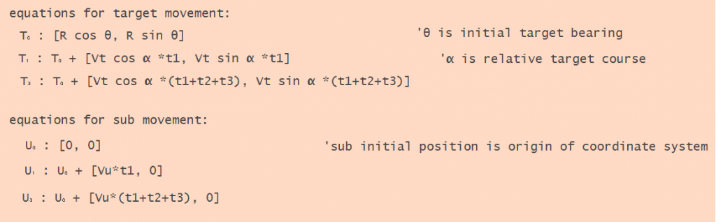
I finally realized that the pursuit of clever geometry shortcuts, is a waste of time. There was no use going over that ground again. I decided to lay out the problem in terms of Cartesian coordinates and a defined x and y axis, and carefully define every known element. This approach, while involving a good deal of work, offered a sure result.
I defined the X-axis to be the axis along which the sub travels, the Y-axis as perpendicular to this. The sub's initial position is 0,0 and moves in a positive direction. The target can be anywhere, so it's coordinates can be positive or negative. The same is true for the torpedo gyro angles and coordinates.
Note, that we seek to find the correct launch bearing for a given gyro angle, not the gyro angle for a given launch bearing.
This shows the general geometry of the problem:
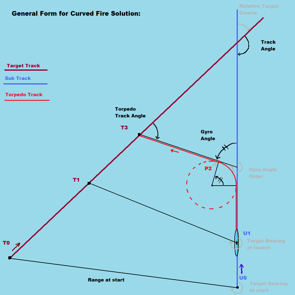
To obtain a solution, I have divided the attack phase into three parts. At the start of the first phase, the sub, U, and target, T, are at their initial positions, and the necessary data for a solution has been compiled. The target and the sub are moving into position for launch.
At the start of the second phase, the torpedo is launched, it runs out, turns, and completes it's turn. In the third phase, the torpedo runs straight ahead on it's final heading, until it impacts with the target. Note that while the target's position, and sub's position at ph2, and the sub position at ph3 (T2, U2, and U3) can be computed, I don't show them here as they don't have any particular tactical significance. The critical thing here is that the torpedo turning phase must be defined separately.
Here is what is known, in math terms:
R is the range to target, at start
Vt is target speed
Vu is sub speed
Vp is torpedo speed
theta is relative target bearing, at start
alpha is relative target course
t1 is time for first phase, (positioning)
t2 is time for second phase, (torpedo turn)
t3 is time for third phase, (torpedo final run)
In order to define the torpedo movement, we must delve into the details of the geometry of the torpedo turn:
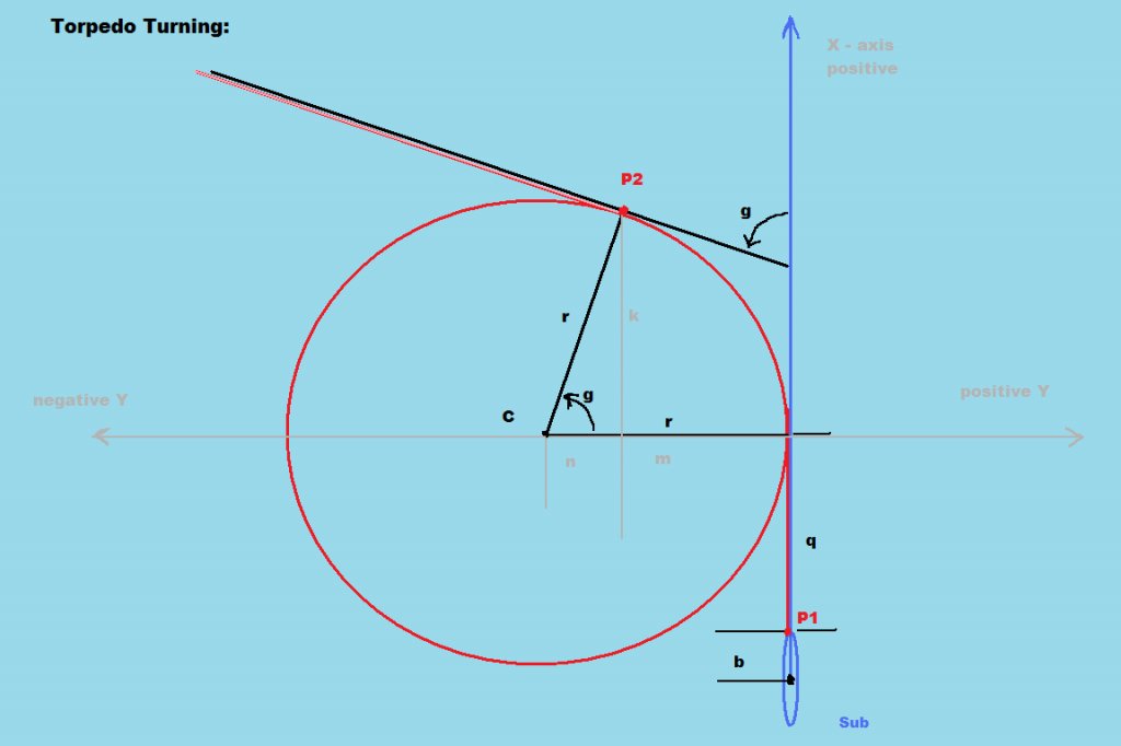
Defining the movement of the torpedo caused me some anxiety until it occurred to me that we don't need to know the location of the torpedo moment to moment, only where it is, as it finishes the turn; an easier matter.
Along the X axis, I broke the turn into 3 segments: the tube distance, b, the torpedo reach, q, and the turn, k. k is easily seen to be equal to r*sin g.
For the displacement along the Y axis, we want to know m. m + n = r and n = r*cos g, so m = r r*cos g = r(1 cos g).
After adding some terms to account for the sign of g, we obtain:

With the torpedo movement elements defined, we can get down to serious business.
By definition, in our firing solution, the position of the torpedo at P3 and the target at T3 will be the same.
Thus:
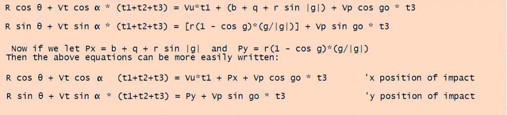
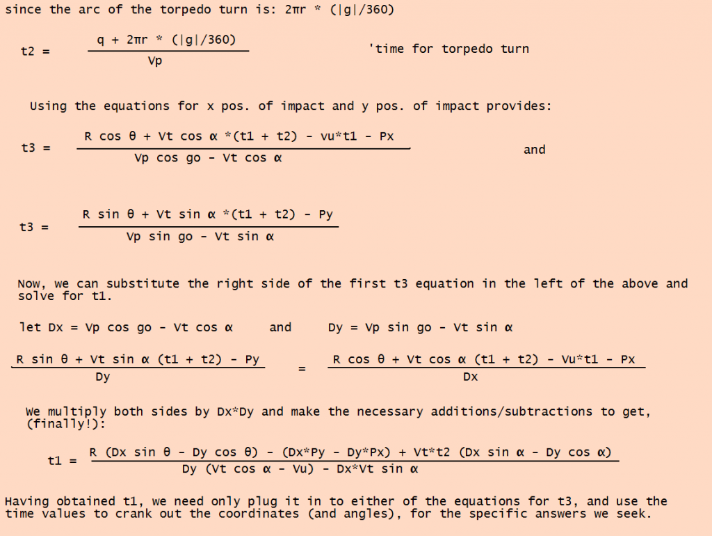
We want to solve for the time variables, t1, t2, t3. Once we know those, we can calculate anything we need, but it appears we have two equations and three unknowns. What to do? Well, since we hammered out the torpedo turn, location and know it's speed, we can calculate t2 at the outset, and eliminate it as an unknown.
Success
From here on, it is a matter of algebra; lots and lots of algebra. As I doubt many here have a strong desire to wade through pages of equations, I won't torture you with a step by step replay. Instead, I'll just show you the highlights.
(Finished in next post)
|