
|
|
SUBSIM: The Web's #1 resource for all submarine & naval simulations since 1997
|
SUBSIM: The Web's #1 resource for all submarine & naval simulations since 1997 |
 02-13-17, 08:19 AM
|
#16 |
|
Sea Lord
 Join Date: Jul 2012
Posts: 1,660
Downloads: 30
Uploads: 0
|
Thanks heaps, La Vache. Appreciated! Too bad I don't read German and Google translate is as hilariously bad as ever but names of books can be looked into. Again thanks heaps.
Reading up on the parallax correction on that other site and he is not making it easy for the reader, that's for sure. |

|

|
|
02-14-17, 03:51 PM
|
#17 |
|
Sea Lord
Join Date: Jul 2012
Posts: 1,660
Downloads: 30
Uploads: 0
|
I am pretty convinced now the bug on the attack map projection is because the developers forgot to mirror the calculations for port vs starboard turns not to mention they add the same distance into the total more than once.
Here is an experiment you guys can do the next time you fire up SH3. Set the TDC up for zero everything except distance. Zero target speed, zero gyro angle, everything. Note down the projected time T0 on the attack map in seconds. Also note down the distance D0 you set the run for. Calculate for 90* port gyro turn the time Tgp: Tgp = (D0 + 95)/D0 * T0 Calculate for 90* starboard turn the time Tgs: Tgp = (D0 - 2*104.5)/D0 * T0 Now turn the periscope to set the gyro angle to 90* port and starboard and compare the projected time with the result you calculated. Were they close? Last edited by Von Due; 02-14-17 at 04:02 PM. |
|
|
|
|
02-15-17, 03:30 PM
|
#18 |
|
Sea Lord
Join Date: Jul 2012
Posts: 1,660
Downloads: 30
Uploads: 0
|
It appears that adding 4 seconds to the runtime for a straight run will give a good approximation for runtime for a 90 degree turn set at the same distance.
The torpedo travels about 100 meters in 4 seconds on fast speed (avg. speed appr. 44.5 kts). The added distance comes from the turn so the arc of the turn must be about 100 meters. Since the arc length for a 90 degree turn a = 1/2 pi*radius, this corresponds to a turn radius of about 63.66 meters which is about 2/3 of the historical accurate turn radius of 95 meters. The torpedo will travel parallell to line of sight to the 270/90 bearings at a distance of roughly 136 meters. It's not exact but should be accurate enough for medium to large size targets. More importantly, the runtime and distance between torpedo track and the 270*/90* bearings are the same for port and starboard turns. Only the projection on the attack map is wrong for starboard turns. Last edited by Von Due; 02-15-17 at 03:56 PM. |
|
|
|
|
02-15-17, 06:30 PM
|
#19 |
|
Electrician's Mate
 Join Date: Nov 2012
Posts: 138
Downloads: 193
Uploads: 0
|
Hallo Von Due
According to Rössler the GA (Gradelaufapparat) could only reach a torpedo running angle of ± 90°. It should be shot with the smallest possible torpedo angle as there was an offset displacement at 90° of ± 35 m. β ≦ 90° You can set settings such as test sheets. As an example rear shot with 7° parallax angle. LfdNo 15 Distance E = 5hm (500m) Target direction ω = 66° Vt = 30 nm/h Vg = 24 nm/h AoB ϫ = 60° StB β = 40° Result = firing angle ϱ = 280° corrected -180° = firing angle 100° The deviation of the deflection angle and the shot angle results in a parallax angle δ ~7° 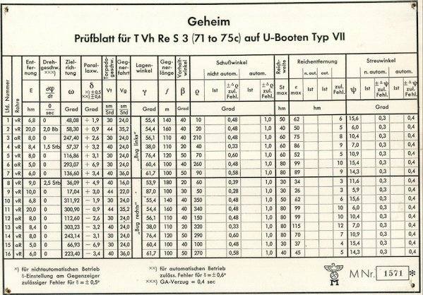 
__________________
youtube |
|
|
|
|
02-15-17, 09:06 PM
|
#20 |
|
Sea Lord
Join Date: Jul 2012
Posts: 1,660
Downloads: 30
Uploads: 0
|
Thanks for that. Has that been verified to work in the game? The main problem with the game is the dimensions that seem to be somewhat off but in a not so predictable way and the main Main issue is the attack map which is way off as a rule of thumb, so to speak. I set up a dummy shot for 3000 meters, gyro angle 315*, intercept angle 135*, target speed 7 kts. The solution projected on the map had a solution for 3750 meters.
Strange also about the 90* only thing as a copy of the commander's handbook has a step by step section on 45* gyro angles if I read that right. |
|
|
|
|
02-16-17, 01:55 PM
|
#21 |
|
Electrician's Mate
Join Date: Nov 2012
Posts: 138
Downloads: 193
Uploads: 0
|
The RW (TDC) shot was the standard solution.
Bow/rear shot, 45° and 90° shot was used in case of TvhRe/TDC failure. Important for complete solution is the Angel of Bow. AoB and lead angle arise with Vt Torpedo running track. For parallax enhancement, Boat speed and command deceleration were automatically calculated. This is probably not considered.
__________________
youtube |
|
|
|
|
02-16-17, 02:31 PM
|
#22 |
|
Sea Lord
Join Date: Jul 2012
Posts: 1,660
Downloads: 30
Uploads: 0
|
In the game, speed, speed changes or course changes are definitely not something the TDC keeps itself updated on. I believe that would be the same for the real German TDC. If anyone other than the Americans had position keeping capable TDC, then that would be interesting to know.
I went back to my main character's campaign, in a Type IXB and the dimensions are definitely different but right now I'm questioning the method that worked for the Type VIIB. Attempting to establish where the equivalent point of fire is for the IXB using G7a torpedos on a 90* setting is giving me a mild headache. |
|
|
|
|
02-17-17, 03:42 PM
|
#23 | ||
|
Electrician's Mate
Join Date: Nov 2012
Posts: 138
Downloads: 193
Uploads: 0
|
Quote:
Quote:
The rotational speed was calculated automatically, but could also be entered manually. The SH3 TDC is a simplification. For example: The spread angle is entered as the target width in meters (100-200). In SH3, enter the angle directly. For Fat and Lut torpedoes there were no adjustments at the TvhRe/S3. These were done directly on the torpedo or on an auxiliary board in the bow space.
__________________
youtube |
||
|
|
|
|
02-24-17, 09:09 AM
|
#24 |
|
Admiral
 Join Date: Feb 2015
Location: Murwik Naval Academy
Posts: 2,122
Downloads: 390
Uploads: 13


|
http://www.tvre.org/en/aiming-with-the-periscope
Try this one out in reference to your parallax issue. Hope it helps.
__________________
[SIGPIC][/SIGPIC] BSTANKO6'S SH5 NAVAL ACADEMY http://www.youtube.com/channel/UCPbe...W2NArCA/videos DISCORD https://discord.gg/6tFeTSUmVc |
|
|
|
|
02-25-17, 06:25 AM
|
#25 | |
|
Hellas
 Join Date: Jul 2008
Posts: 2,325
Downloads: 182
Uploads: 7
|
hello Von Due,
i think it is useless trying to find out great accuracy based on sh3's TDC for two reasons. The first reason is that the game (and eventually TDC) is NOT getting the distance to target or bearing to target from the periscope (the one that player is using) but from the generic node of sub's 3d model. this ,practically, mean that for each sub model there will be different inaccuracies. you can easily confirm that by looking at a stationary -close to you- target from periscope at a fixed bearing. not at bearing 0° but better,for example, to 270° and watch the bearing that TDC shows.you will need a mod for showing you the 10ths of degrees of bearing for that.then simply,without moving anything, press the lock button to lock the target on periscope and watch that the bearing on TDC is slightly changing and now the bearing on TDC is not exactly the same with the bearing you see on scope. (this is fixable.in my own sh3 set up , i have matched ,at the uboat i am using,all the scopes-uzo 3d nodes with the uboat's generic node for avoiding the above inaccuracies) the second reason is that sh3 is coming from sh2 which is coming from sh1. sh1 is for american submarines and sh3 is for german submarines. The american submarines were using different Torpedo's Straight Run(SR) and Torpedo's Turn Radious(TR) values for the left or right shots (from this book:https://www.abebooks.com/97819353270...1935327070/plp i read that for right shots the values were SR=57.93yards TR=215yards and for left shots the values were SR=32.46yards TR=206yards). I am suspecting that the sh's devs didn't transform the equations (for torpedo aiming) right from sh1 to sh2 and finally to sh3. i am ,also, guessing that this is the reason for the inaccuracies you see at torpedo running times for shots like in the following image (the first reason is not responsible for that issue.this issue is a hardcode error):  the image shows the TDC solution at two symmetrical set ups. at the left, you see that torpedo's run time is 1:13 and at the left you see that torpedo's run time is 1:06. the two solutions have to be the same but they are not. ps: propably i am off topic (haven't followed all the posts) but my point is that trying to get very accurate results(-conclusions) based on sh3's TDC is not a safe way. Quote:
__________________
Knowledge is the only thing that nobody can ever take from you...  Mediafire page:http://www.mediafire.com/folder/da50.../Makman94_Mods |
|
|
|
|
|
02-25-17, 07:42 AM
|
#26 |
|
Sea Lord
Join Date: Jul 2012
Posts: 1,660
Downloads: 30
Uploads: 0
|
Greatly appreciated post, makman94. As you said, there are errors and the attack map and TDC are both questionable. The goal I would like to reach however is to figure out a way to manually plot lead angles for gyro angled shots, for various speeds and distances. Manually, because a bugged game is not going to do what it's supposed to so in short, find a way to work around the bugs and errors in the game.
|
|
|
|
|
02-27-17, 04:29 AM
|
#27 | |
|
Hellas
Join Date: Jul 2008
Posts: 2,325
Downloads: 182
Uploads: 7
|
Quote:
there is a workaround though for those who doesn't want to use the tdc and it is called ''the broken tdc methods'' (http://www.subsim.com/radioroom/showthread.php?t=169935) but in these methods is not taking in account the parallax correction so there will be inaccuracies in very close shots.The method is good for use at shots more than 1500m At the tutorials for these methods (tutorials can be found in MaGui F.rar), i showed the straight shots and the perfect shots (perfect shot means impact angle = 90°) but you can combine these two methods and create whatever curved shot you like (for any other curved shot you have to choose the desired impact angle-instead of 90°- and proceed). in case that you are interested in these methods , have in mind to take the angle 'x' ,always and in any case, from the tables (not from the RAOBF rings as i am discribing in the notes.the RAOBF rings are good for getting angles <5.71° but if angle 'x' is greater the rings will be off. so get the angle 'x' only from tables) here is one example how these two methods can be combined:  steps for the above example: 1. get angle lb1 from map (angle lb1 is the angle between yours and target courses).lets say at our example lb1=110° 2. select the impact angle (angle lb2) that you want for your shot (at perfect shots this angle is 90°). then set to gyro G=lb1-lb2 .then set tdc to manual mode from now on. in our example . lets select impact angle lb2= 80° so we will have G=110°-80°=30° so will set G=30°to tdc and switch it to manual mode from now on. 3. choose the torpedo speed that you will use and look at its table for getting the angle 'x'. for this combined method,the torpedo tables now have at vertical columns the angles lb2. so find the lb2 of our example at vertical columns and the target speed at horizontal lines. the table will give you the angle 'x'. lets say that our target is moving with speed= 10 knots and we choose to hit him with a 30kts torpedo.from the table,lb2=80° and u=10, so we get angle 'x'=17.2° 4. Shooting bearing = G + x so ,at our example, Shooting bearing = 30° + 17.2° = 47.2°
__________________
Knowledge is the only thing that nobody can ever take from you... Mediafire page:http://www.mediafire.com/folder/da50.../Makman94_Mods |
|
|
|
|
|
02-27-17, 06:20 AM
|
#28 |
|
Sea Lord
Join Date: Jul 2012
Posts: 1,660
Downloads: 30
Uploads: 0
|
Just curious. Those tables you show there (I have them too), how were those values found? Were they all empirically found or were there some sort of algorithm involved? If they were all empirically found then I am impressed! That's a lot of testing.
|
|
|
|
|
02-27-17, 11:21 PM
|
#29 | |
|
Hellas
Join Date: Jul 2008
Posts: 2,325
Downloads: 182
Uploads: 7
|
Quote:
if you apply the law of sines on the triangle that containes the angle 'x' (look at the image at my previous post) you get : x = arctan{sin(lb2) / [(u1/u2) + cos(lb2)]} ,where u1=torpedo speed and u2=target speed and excel gave all the outputs that you see on tables. (i ,then, rounded these outputs to one decimal digit before print them one tables)
__________________
Knowledge is the only thing that nobody can ever take from you... Mediafire page:http://www.mediafire.com/folder/da50.../Makman94_Mods |
|
|
|
|
|
02-28-17, 01:14 AM
|
#30 |
|
Sea Lord
Join Date: Jul 2012
Posts: 1,660
Downloads: 30
Uploads: 0
|
This is where I am confused. See, you said there was no simple way of correcting for parallax but for these angles to really work in-game, the parallax MUST have been accounted for. See the contradiction? That there is a parallax issue in the game, like in the real world, has been confirmed. The game does account for the different positions of tube muzzles, periscopes, advance and equivalent point of fire. That does not imply in any way that the dimensions the game use are the historically accurate dimensions. It only means that the game does distinguish between bearing from tube muzzle and bearing from periscope and that these 2 bearings are different from one another. Tests show that the game does apply the concept of equivalent point of fire, in one shape or the other, even if the game does not follow up on the concept in full.
It does nothing good in knowing what lead angle the torpedo needs, if there is no way the game will allow the player to know how to correct for parallax. This is the reason I asked if these angles were empirically found. To use your example: The triangle shows the lead angle for the torpedo must be 17.2 degrees. This does not help the player as 17.2 degrees is only valid as seen from the equivalent point of fire. From the periscope, the lead angle must be different (smaller in fact) than 17.2. How much smaller is the unknown and the challenge is to find out exactly how to find the lead angle as seen from the periscope. Last edited by Von Due; 02-28-17 at 02:34 AM. |
|
|
|
 |
|
|


 Linear Mode

