
|
|
SUBSIM: The Web's #1 resource for all submarine & naval simulations since 1997
|
SUBSIM: The Web's #1 resource for all submarine & naval simulations since 1997 |
 09-17-17, 04:12 PM
|
#1 |
|
Hellas
 Join Date: Jul 2008
Posts: 2,325
Downloads: 182
Uploads: 7
|
Hello subsimers,
does anyone knows where i can find the manual of Bearing Rate Computer? (http://www.subguru.com/BRC.jpg)
__________________
Knowledge is the only thing that nobody can ever take from you...  Mediafire page:http://www.mediafire.com/folder/da50.../Makman94_Mods |

|

|
|
09-18-17, 03:12 AM
|
#2 |
|
Bosun
 Join Date: Nov 2011
Posts: 68
Downloads: 63
Uploads: 0
|
Coppied from http://www.subsim.com/radioroom/showthread.php?t=233393
From what I read and managed to figure out, the BRC works like this: 1) construct LOS diagram 2) you know target relative bearing - you know the first angle of which sine is needed 3) find target's AOB - you now know the second angle of which sine is also needed 4) find target's speed 5) find target's bearing rate now: - since you know ownship speed, point 90 degree mark (innermost disk) on that speed and read speed across the LOS where target bearing angle is - this is the first speed component. You multiplied your speed by sinus of target bearing angle. - do the same with target's speed and AOB - add both speeds to get total relative speed across the LOS - turn bearing rate value to that calculated speed - read the range estimation In my opinion that is the basic principle of BRC operation. OFC this is only my guess from what I read, but it's quite possible they did it like this. I think we should ask Admins to move the original thread and continue here. |
|
|
|
|
09-18-17, 04:37 PM
|
#3 | |
|
Hellas
Join Date: Jul 2008
Posts: 2,325
Downloads: 182
Uploads: 7
|
Quote:
 i think that i am very close getting to it but still haven't totally got it  for example, the time between the two bearings must be fixed at 1 minute (for using the tool) or i am free to time as much i want between the two bearings ? also you say ''You multiplied your speed by sinus of target bearing angle'' ,the question is that this calculation will be done with a digital calculator ? The final range etsimation output of the tool is the range at first bearing or something else? [i am suspecting that the 'key' value to be calculated is the segment ED(which can easily be found).Then , with the law of sines on triangle ADE , the range at first bearing (AD) can finally be calculated] -- see at the pic if it is not big deal for you , i would like you to make a graph showing ,with an example, all the above .that will help very much and ,for sure, clear all my questions ps: Have a look at this (did i understand right your data?): 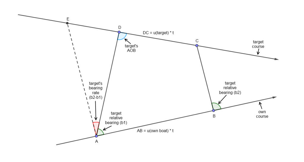
__________________
Knowledge is the only thing that nobody can ever take from you... Mediafire page:http://www.mediafire.com/folder/da50.../Makman94_Mods Last edited by makman94; 09-18-17 at 05:06 PM. |
|
|
|
|
|
09-19-17, 01:28 AM
|
#4 | |||
|
Bosun
Join Date: Nov 2011
Posts: 68
Downloads: 63
Uploads: 0
|
Hi!
Quote:
Also you can predict future data to enter to BRC and calculations will be valid when your target behave according to your predictions and is where you supposed it to be. So bearing rate entered to BRC can be just fair enough mean based on most recent data. The closer the target - the more rapid change in bearing rate. So for distant contacts BR can be determined based on more time and for closer contacts it must be determined for less time. Bearing changes over time as arcustangent function and bearing rate as its derivative 1/(1+x^2). Quote:
We must obtain total relative speed across the LOS which is made of ownship speed across the LOS and target's speed across the LOS. Across the LOS (ATL) means the speed component perpendicular to LOS. From trigonometry we know that to obtain component perpendicular (x) we must multiply base speed by sine of angle. Own component ATL is ownspeed * sine target bearing. So we point innermost disk's 90 degree on ownspeed and read what speed is where target bearing is. The same for target - you use target speed (obtained by any other means) and Angle on bow. Bearing is relative +-180 at each side. Also remember that sin(angle) = sin (180-angle). Quote:
sorry atm I have no option to draw anything, maybe later. Edit: made a mistake writing that bearing rate changes as tangent function. Corrected. Last edited by B_K; 09-19-17 at 06:47 AM. |
|||
|
|
|
|
09-21-17, 12:47 AM
|
#5 | |
|
Hellas
Join Date: Jul 2008
Posts: 2,325
Downloads: 182
Uploads: 7
|
Quote:
 Never mind for the rest B_K , i figured out what i wanted to know about the use of this tool Many thanks for your help mate 
__________________
Knowledge is the only thing that nobody can ever take from you... Mediafire page:http://www.mediafire.com/folder/da50.../Makman94_Mods |
|
|
|
|
|
09-21-17, 02:07 AM
|
#6 |
|
Bosun
Join Date: Nov 2011
Posts: 68
Downloads: 63
Uploads: 0
|
Here is also a superb mathematical approach to bearings only TMA, including Ekelund ranging and Spiess method. Using the BRC helps to solve final equations very quickly.
http://ricojansen.nl/downloads/NOE_-...s_Only_TMA.pdf |
|
|
|
|
09-23-17, 07:14 PM
|
#7 | |
|
Hellas
Join Date: Jul 2008
Posts: 2,325
Downloads: 182
Uploads: 7
|
Quote:
yes , i have this document too and it is ,indeed, one of the best around
__________________
Knowledge is the only thing that nobody can ever take from you... Mediafire page:http://www.mediafire.com/folder/da50.../Makman94_Mods |
|
|
|
|
|
09-25-17, 03:17 PM
|
#8 |
|
Silent Hunter
  Join Date: Dec 2004
Location: AN9771
Posts: 4,892
Downloads: 300
Uploads: 0
|
This document also has some information on how to use a BRC in combination with a bearing rate plot:
http://www.globalsecurity.org/milita...14308_ch10.pdf |
|
|
|
|
09-26-17, 02:55 AM
|
#9 |
|
Bosun
Join Date: Nov 2011
Posts: 68
Downloads: 63
Uploads: 0
|
Yeah, thanks. Originally this thread was in SH3 section, and the document was linked there. Next Makman copied the thread to DW section and discussion moved here, but we didn't copy all posts. It would be good if Admin merged both threads in one place.
Any more documents will be appreciated, though. I find it hard to find something more than documents on TMA/BRC that we mention in this thread. |
|
|
|
 |
|
|


 Linear Mode

