I have just come back to SH after a while away, and I dimly remembered that it was possible to get target tracks exclusively via hydrophone while still moving. After looking around a bit, I finally rediscovered kuikueg's 4 bearing method document, and Makman99's video of how to pull it off in SH3. But unfortunately neither really gives a super easy set of instructions on how to do it in game, and kuikueg's geometry makes my brain hurt. So I set out to break it down Barney-style. Have a look, and tell me what you think.
Kuikueg's 4-bearing method for a moving Sub.
I am using MoBo as a plotting tool here, because it is easier to switch and do screen snips between it and this document. Note that due to not having a zoom feature, Mobo is not as precise as is possible in game at full zoom. Therefore it is possible that my answers at the end in terms of target heading and speed are not quite as accurate as would be achieved by carefully plotting in-game. My objective here is to show the steps, I am sure you will be entirely accurate and get good results. Also note that throughout the process I tell you to labels points thisly and thusly, but it totally doesn't matter, and you don't have to label a damn thing if you don't want to!
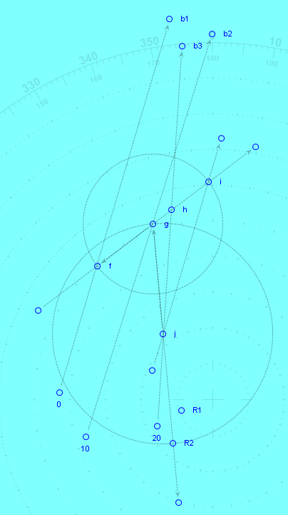
1. Take 3 bearings at regular time intervals. Changes in own bearing/speed/position are completely immaterial, but the intervals must be as precise as possible.
2. Scribe a random line that crosses all three bearing lines. Label intersections on b1 at (a), b2 at (b), and b3 at (c).
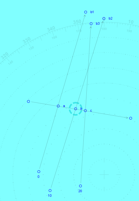
3. Draw a circle centred on (b) with radius endpoint at (a). Label the point on the line at the opposite side of circle from (a),as (d).
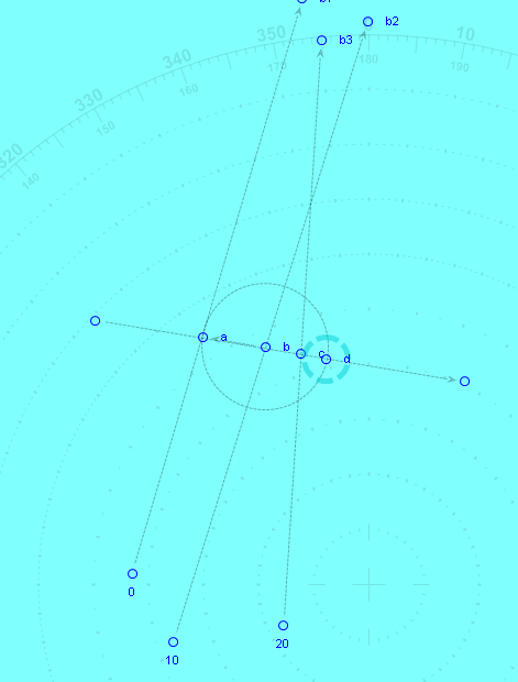
4. Draw a line parallel (easiest using the compass and dragging it) to b1, and place it so that it intersects with (d). Find the point this line intersects with b3, and label it (e).
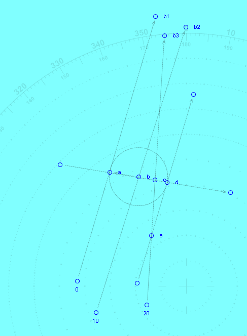
5. Draw a line through (b)-(e), then draw a circle centred on (e) with radius endpoint at (b). Label the opposite side of the circle on line (b)-(e) as (R1). (R1) is your first “red line” point.
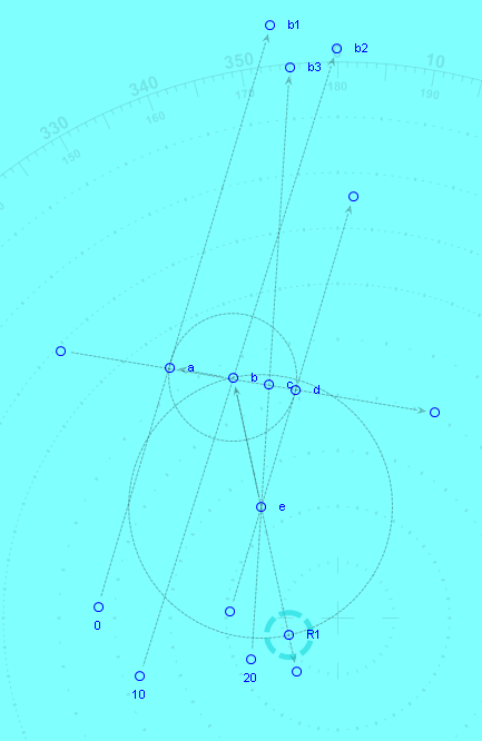
6. Repeat steps 1-4, but with a different random line thorough b1, b2, and b3. Label the resultant point R2.
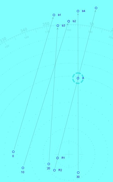
7. Draw a line from R2 extending through R1. Then take another bearing at the regular interval, b4. It is helpful here to ensure that your own bearing changes between the b3 and b4 measurements if you have been previously travelling at a consistent speed/bearing; this will aid in the triangulation of the target position. Find the intersection with the “red line” extending through R1-R2, and mark it (A). This is the exact current position of the target.
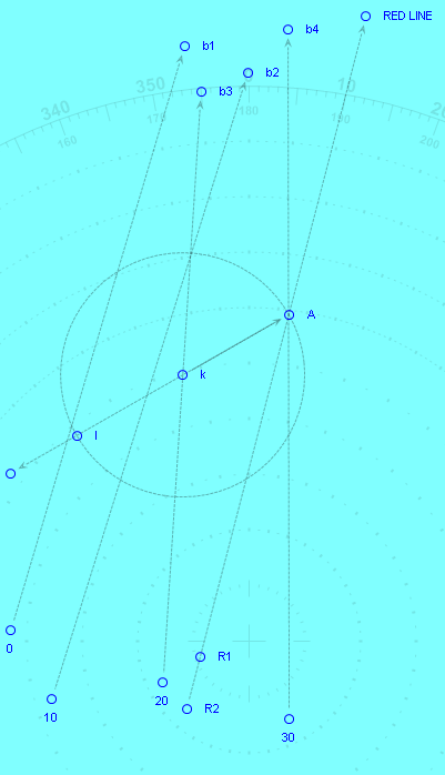
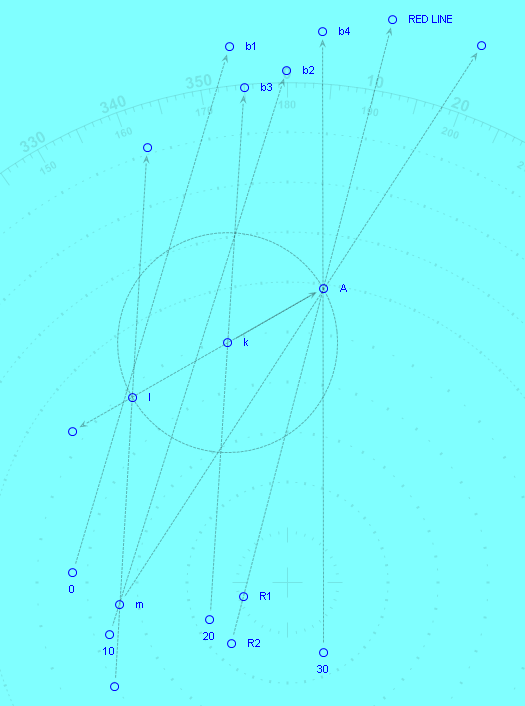
8. In order to find target course, draw a random line from (A) that intersects b3 anywhere along its path. Label the intersection of this line and b3 as (k). Draw a circle radius (k)-(A), and mark the spot on the line at the opposite end of the circle as (l).
9. Similar to step 3, above, draw a line parallel to b3, passing through (l). Find the point at which this line passes through the b2 line, and label it (m).
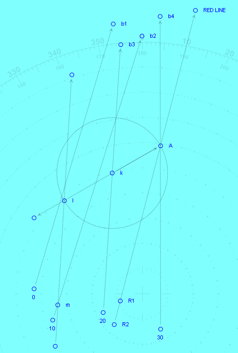
10. Draw a line from (m) through (A). This line indicates the exact course of the target, from which can be gained speed and AoB.
11. After a bit of tidying up, we can plot and measure the intersection points with the b1-b4 bearing lines, and use our speed tables to get the target speed, and use our compass to get the bearing. In this case, using the MoBo application gets us a target heading of approx 33 degrees true, approx 3800m between b3 and b4 intervals, which with a 10 min bearing interval gives us a speed of approx. 11.3 knots. Definitely enough to get you close.
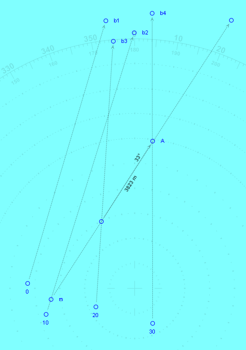
12. Note that for this exercise I picked totally random start points and bearings, and used the MoBo to plot. In real life for this solution with the sub actually at the “0” mark, the b1 bearing would have been a back bearing of that indicated, as the target would have passed by the sub on its way to (m) between the b1 and b2 bearings. This would have changed how steps 1-6 looked, but, amazingly, would not have changed line through R1-R2, or the outcome, at all. Therefore, it is perfectly ok at any point to extend the bearing lines infinitely, and draw your random intersection lines at any point along the infinite bearing lines, so long as the relevant intersection points are generated.
Hope this is helpful, and let me know if you spot any errors!